Controller of injection molding machine

A technology for injection molding machines and controllers, applied in the field of injection molding machines, can solve the problems of difficult control, increased injection pressure dispersion or minimum buffer volume, and inability to inject molten resin, etc.

Active Publication Date: 2009-04-29
FANUC LTD
View PDF14 Cites 0 Cited by
  • Summary
  • Abstract
  • Description
  • Claims
  • Application Information

AI Technical Summary

Problems solved by technology

However, there is a problem that a delayed operation of a backflow prevention device such as a valve for preventing backflow of molten resin may cause backflow of the molten resin, thereby failing to inject an accurate amount of the molten resin
This increases the dispersion or minimum cushioning of the injection pressure, which is also difficult to control

Method used


Image

  • Controller of injection molding machine
  • Controller of injection molding machine
  • Controller of injection molding machine

Examples


Embodiment Construction

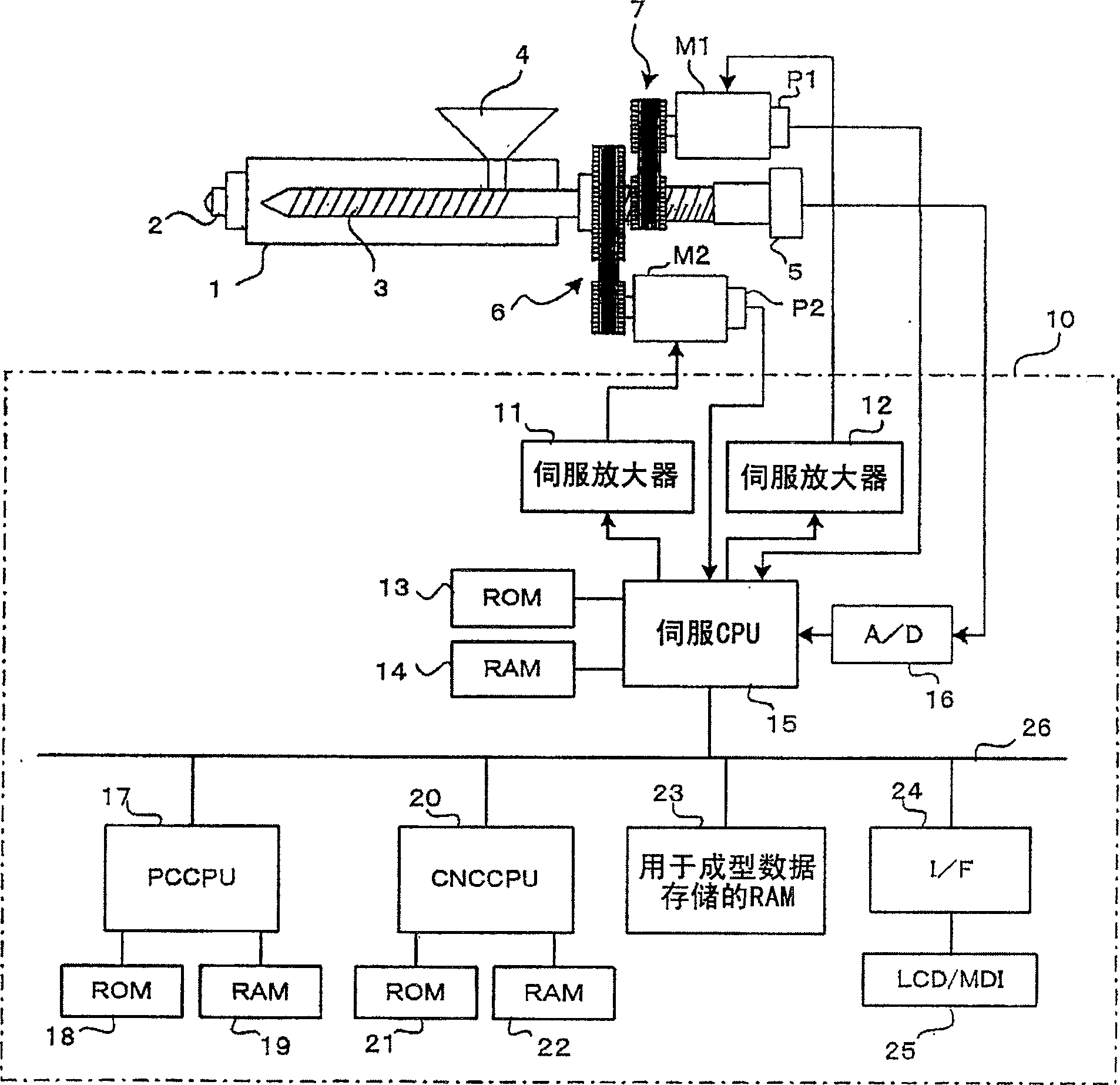
[0033] figure 1 Main components of an injection molding machine according to an embodiment of the present invention are shown. The nozzle part 2 is pasted on the end of the injection barrel 1, and the screw 3 passes through the injection barrel 1. The screw 3 has a pressure sensor 5 such as a load cell for detecting the resin pressure acting on the screw 3 . A servo motor M2 for screw rotation rotates the screw 3 through a transmission mechanism 6 (consisting of pulleys, conveyor belts, etc.). Further, the servo motor M1 used for the forward and backward movement of the screw drives the screw 3 to move in its axial direction through the transmission mechanism 7, which includes a pulley, a conveyor belt, a ball screw / nut mechanism, and a mechanism for converting rotational motion into linear motion. some other agencies. Symbol P1 represents a position / speed detector that detects the shaft position and speed of the screw 3 by detecting the position / speed of the servo motor M1...


PUM


Abstract

A control pillar of injection molding machine, which can diminish the increase of cycle time while the screw rod is falling back after be measured, more accuracy and unity numerical magnitude can be obtained, and the condition of measurement can be determined in a short time. After the measuring, screw rod stop circumgyrate and fall back by the first velocity V1. In the enactment zone, the screw rod reverse rotation by the preset velocity Rv. Then, screw rod fall back at he second velocity V2 which is lower than the first velocity V1, While stopped in the reverse rotation zone, screw rod stop circumgyrate and fall back to the enactment stop position by the third velocity V3. Therefore, compared to the circs of screw rod fall back and reverse rotation, cycle time can be shorten. When the screw rod reverse rotation the fall back speed of screw rod is low, which can inhibit the sudden change of drang. as a consequence of adjust the conditional of screw rod reverse rotation and retrogressive autocephaly, it can be adjust to optimum conditions in a short time.

Description

technical field [0001] The invention relates to an injection molding machine, in particular to a controller of the injection molding machine for accurately measuring resin. Background technique [0002] In a screw direct injection molding machine, a screw in a heated barrel is rotated to melt and shape a resin material, and then the molten resin is fed under pressure into the end portion of the heated barrel. Then, the screw retreats under pressure control. When the screw reaches the set measuring point, it stops rotating and retreats, and then measures the amount of resin. Also, in preplasticized injection molding machines, molten resin is fed into the end portion of the barrel, and the piston is retracted under the pressure of the injected resin. Measure the amount of resin when the piston reaches the set position. After measurement, a screw or piston advances to inject and fill the mold with molten resin. [0003] In order to improve the quality of molded products, it...

Claims


Application Information

Patent Timeline
Patent Type & Authority Patents(China)
IPC IPC(8): B29C45/76B29C45/50
Inventor 白石亘石黑俊夫高次聪内山辰宏渡边广川崎达也丸山淳平
Owner FANUC LTD
Why Eureka
Try Eureka