Gas blowing type negative pressure air-suction device

A gas injection and air suction device technology, which is applied to jet pumps, non-displacement pumps, machines/engines, etc., can solve problems such as difficulty in noise production process, and achieve the effects of facilitating product process production, reducing process costs, and simple structure

Inactive Publication Date: 2009-05-27
深圳市旋风流体科技有限公司
View PDF7 Cites 2 Cited by
  • Summary
  • Abstract
  • Description
  • Claims
  • Application Information

AI Technical Summary

Problems solved by technology

[0004] However, the inventor found in further practice that the above-mentioned invention still has certain noise problems and difficulties in the manufacturing process, and its structure still needs to be further improved to meet higher practical requirements.

Method used


Image

  • Gas blowing type negative pressure air-suction device
  • Gas blowing type negative pressure air-suction device
  • Gas blowing type negative pressure air-suction device

Examples


Embodiment 1

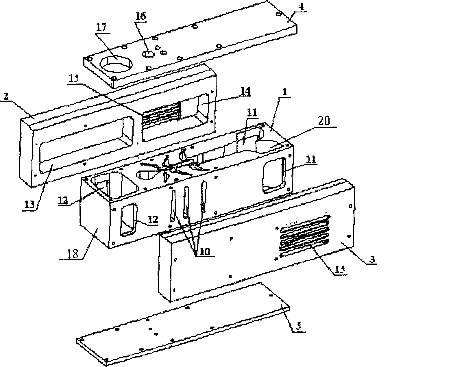
[0020] Embodiment 1, a kind of gas injection type negative pressure suction device, such as figure 1 with figure 2 As shown, it includes: spray plate seat 1, left side plate 2, right side plate 3, upper cover plate 4 and lower cover plate 5. Among them, the gas injection type negative pressure suction device is based on the injection plate base 1, and the left side plate 2, the right side plate 3, the upper cover plate 4, and the lower cover plate 5 are all fixed on the injection plate base 1 by screws. The joint surfaces of plate 2, right side plate 3, upper cover plate 4, lower cover plate 5 and spray plate seat 1 are provided with gaskets or coated with sealant to ensure better sealing effect.

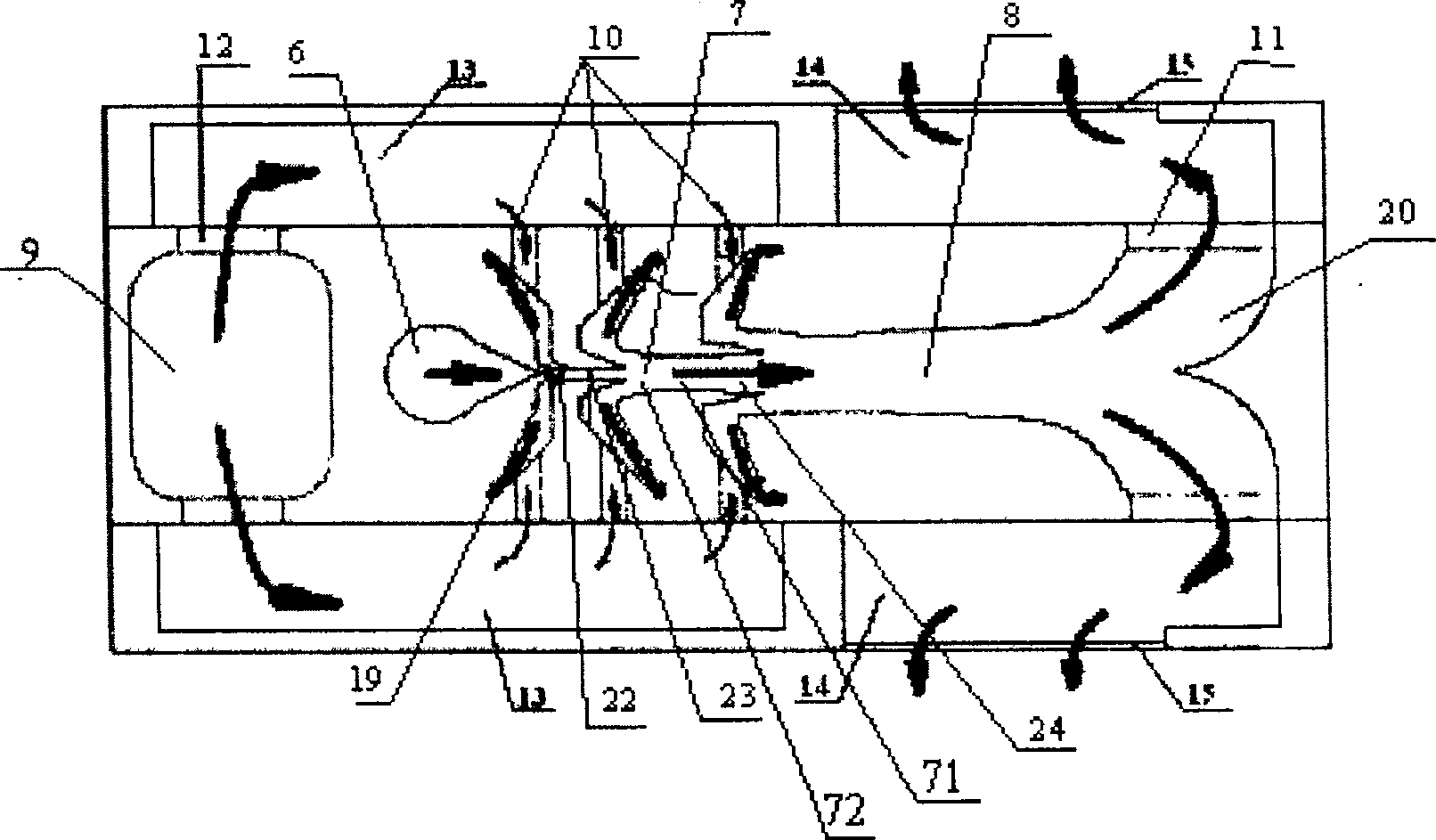
[0021] combine figure 1 with figure 2 , A vacuum chamber 9 , a pressure chamber 6 , an injection channel 7 , an exhaust channel 8 and an exhaust chamber 20 are provided in sequence from back to front on the injection plate base 1 . A partition is provided between the vacuum ch...

Embodiment 2

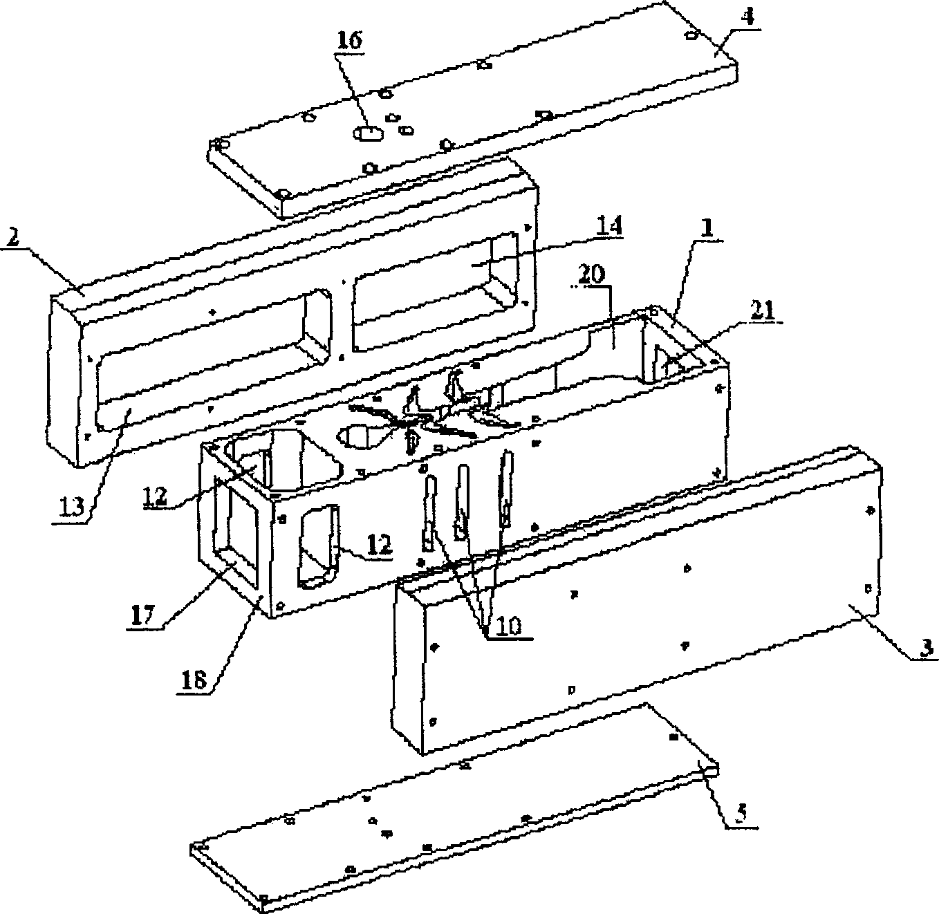
[0024] Embodiment 2, another kind of gas injection type negative pressure suction device, such as image 3 with Figure 4 As shown, the difference between this embodiment and Embodiment 1 is that the external vacuum port 17 is moved from the upper cover plate 4 to the injection plate seat 1, and no external exhaust is provided on the left side plate 2 and the right side plate 3. Port 15, but directly on the front end injection plate seat 1 of the expanded exhaust chamber 20, exhaust hole 21 is set (certainly, also can offer external exhaust port 15 on left side plate 2 and right side plate 3 simultaneously. ). Of course, other structures are the same as in Embodiment 1.


PUM


Abstract

A gas blowing negative pressure suction device comprises vacuum chamber 9, pressure chamber 6, ejection channel 7, negative pressure suction channel 10, exhaust channel 8, sprinkler plate 1, left side board 2, and right side board 3. Said pressure chamber 6, ejection channel 7 and exhaust channel 8 are set on the sprinkler plate 1 and they communicate with each other. Said vacuum chamber 9 is set on the front of the sprinkler plate 1, the negative pressure suction channel 10 is symmetry set on the side wall of the ejection channel 7, a one-way valve 19 is set on the negative pressure suction channel 10, a front chamber 13 and a behind chamber 14 are symmetry set on the left side board 2 and right side board 3 to make one end of chamber 13 connect to the channel 10, the other end of chamber 13 connect to the chamber 9, the behind chamber 14 connect to the channel 8, when the board 2 and board 3 cover the sprinkler plate 1. The invention provides a gas blowing negative pressure suction device with low noise, simple construction, and easy production.

Description

【Technical field】 [0001] The invention relates to a vacuum obtaining device, in particular to a negative pressure suction device. 【Background technique】 [0002] Existing gas jet negative pressure inhalation devices all use circular tube-shaped injection channels. When the flow rate increases, it is generally realized by increasing the diameter of the circular tube or increasing the number of injection channels. However, when the diameter of the circular tube increases to a certain extent, its suction efficiency will drop significantly. Therefore, when the flow rate does not increase much, the method of increasing the diameter of the circular tube can be used to achieve it. If the flow rate continues to increase, it can only be achieved by increasing the number of injection channels, but this is not an unlimited increase. Because as the number of channels increases, it is difficult for the ejection channels arranged in the center to suck gas from the outside on the one hand...

Claims


Application Information

Patent Timeline
Patent Type & Authority Patents(China)
IPC IPC(8): F04F5/20
Inventor 汪京涛李天维
Owner 深圳市旋风流体科技有限公司
Why Eureka
Try Eureka