Supercharge Your Innovation With Domain-Expert AI Agents!

Radiator

一种散热器、散热鳍片的技术,应用在散热片、间接换热器、仪器等方向,能够解决降低散热鳍片与强制气流热交换效率等问题

Inactive Publication Date: 2009-05-27
FU ZHUN PRECISION IND SHENZHEN +1
View PDF4 Cites 0 Cited by
  • Summary
  • Abstract
  • Description
  • Claims
  • Application Information

AI Technical Summary

Problems solved by technology

Even in turbulent flow, there is a laminar bottom layer at the contact part between the fin surface and the forced air flow, and the increase in the thickness of the laminar bottom layer will reduce the heat exchange efficiency between the cooling fins and the forced air flow

Method used


Image

  • Radiator
  • Radiator
  • Radiator

Examples


Embodiment Construction

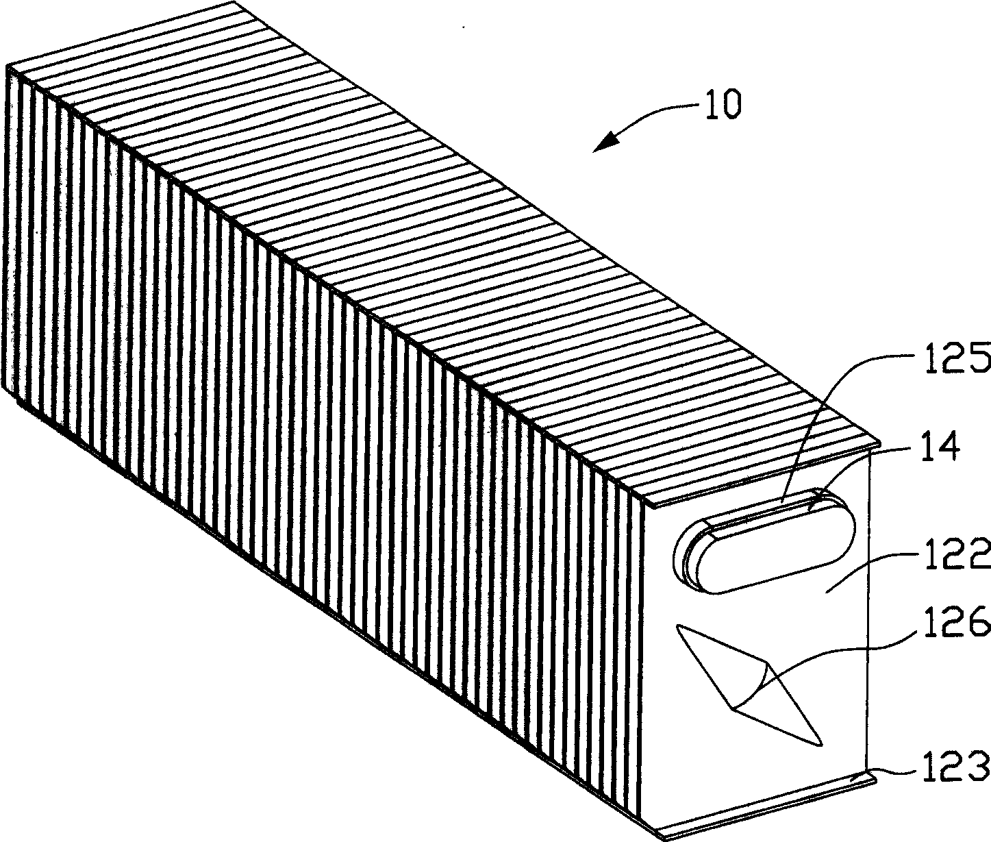
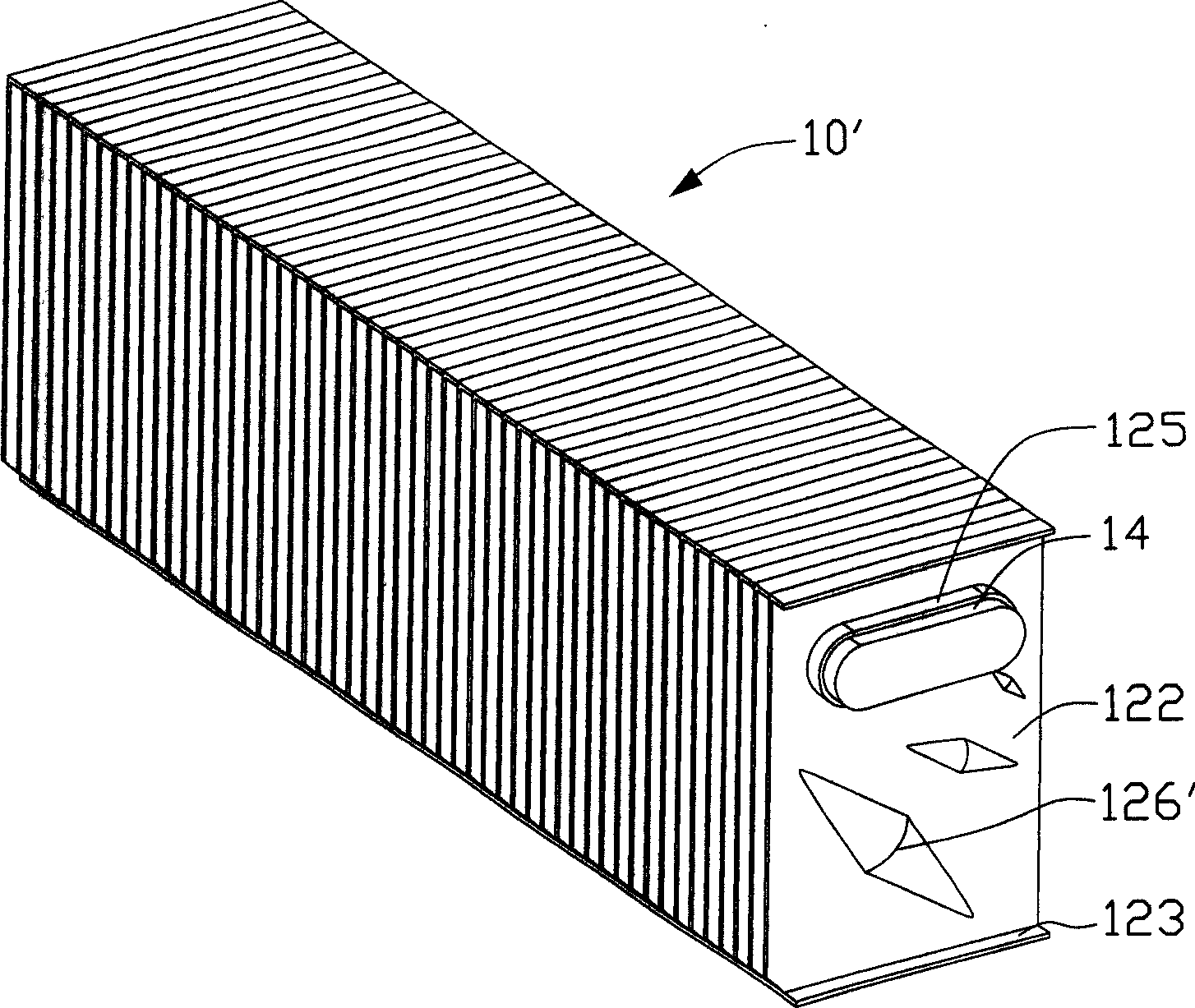
[0013] The radiator 10 of the present invention can be used in conjunction with a cooling fan, so that the airflow generated by the cooling fan blows towards the radiator 10 in a certain direction. Such as figure 1 and figure 2 As shown, the heat sink 10 includes a fin group formed by stacking a plurality of parallel cooling fins 12 and a heat pipe 14 passing through the fin group. The heat pipe 14 can be in contact with a heating element, and the The heat generated by the heating element is transferred to the fin set.

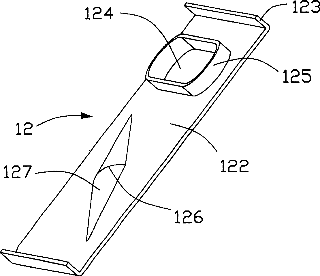
[0014] The cooling fins 12 include a rectangular body 122, the upper and lower ends of the body 122 are respectively bent to form fins 123 perpendicular to the body 122, and the fins 123 of each cooling fin 12 are respectively connected to the previous cooling fin. The bodies 122 of the heat dissipation fins 12 are abutted against each other, so that there is a certain distance between two adjacent heat dissipation fins 12 , so that an airflow channel throu...


PUM


Abstract

A heat sink ( 10 ) includes a plurality of fins ( 12 ). Each of the fins includes a main body ( 122 ) and at least one bulge ( 126 ) disposed on the main body. The main bodies of two adjacent fins cooperatively define an air passage ( 121 ) therebetween, for allowing an airflow to pass therethough. The bulge has a varying projection height so as to form a streamline guide surface ( 127 ) thereon.

Description

【Technical field】 [0001] The invention relates to a heat sink, in particular to a heat sink with high heat dissipation efficiency. 【Background technique】 [0002] Existing cooling devices generally include a radiator and a cooling fan for providing forced airflow. The heat sink is provided with a plurality of plate-shaped heat dissipation fins, wherein an airflow passage for the forced airflow to pass is formed between each adjacent heat dissipation fin, and the heat dissipation device utilizes the heat exchange between the forced airflow in the airflow passage and the heat dissipation fins. Realize heat dissipation of heat-generating electronic components. [0003] During the heat dissipation process of the heat dissipation device, due to the influence of viscosity, the forced air flow in the air flow channel is a laminar flow or a turbulent flow. Usually turbulent flow enhances the heat exchange between the cooling fins and the forced air flow. Even when the flow is tur...

Claims


Application Information

Patent Timeline
Patent Type & Authority Patents(China)
IPC IPC(8): H05K7/20G12B15/04
CPCF28D15/0275F28F1/24H01L23/467F28F13/06F28D15/0266H01L23/3672F28D15/0233F28F2215/10H01L2924/0002H01L2924/00
Inventor 黄清白朱习剑
Owner FU ZHUN PRECISION IND SHENZHEN
Features
  • R&D
  • Intellectual Property
  • Life Sciences
  • Materials
  • Tech Scout
  • Unparalleled Data Quality
  • Higher Quality Content
  • 60% Fewer Hallucinations
Learn More