Transistor with magneto resistnace

A magnetoresistance and transistor technology, applied in the field of magnetoresistance transistors, can solve problems such as high production cost, difficulty in miniaturization of structure, and difficult process

Inactive Publication Date: 2009-06-03
IND TECH RES INST
View PDF6 Cites 0 Cited by
  • Summary
  • Abstract
  • Description
  • Claims
  • Application Information

AI Technical Summary

Problems solved by technology

The magnetoresistive transistor provided by the present invention solves a series of problems existing in the current magnetoresistance transistor, such as difficult structure miniaturization, difficult process, and high production cost.

Method used


Image

  • Transistor with magneto resistnace
  • Transistor with magneto resistnace
  • Transistor with magneto resistnace

Examples


Embodiment Construction

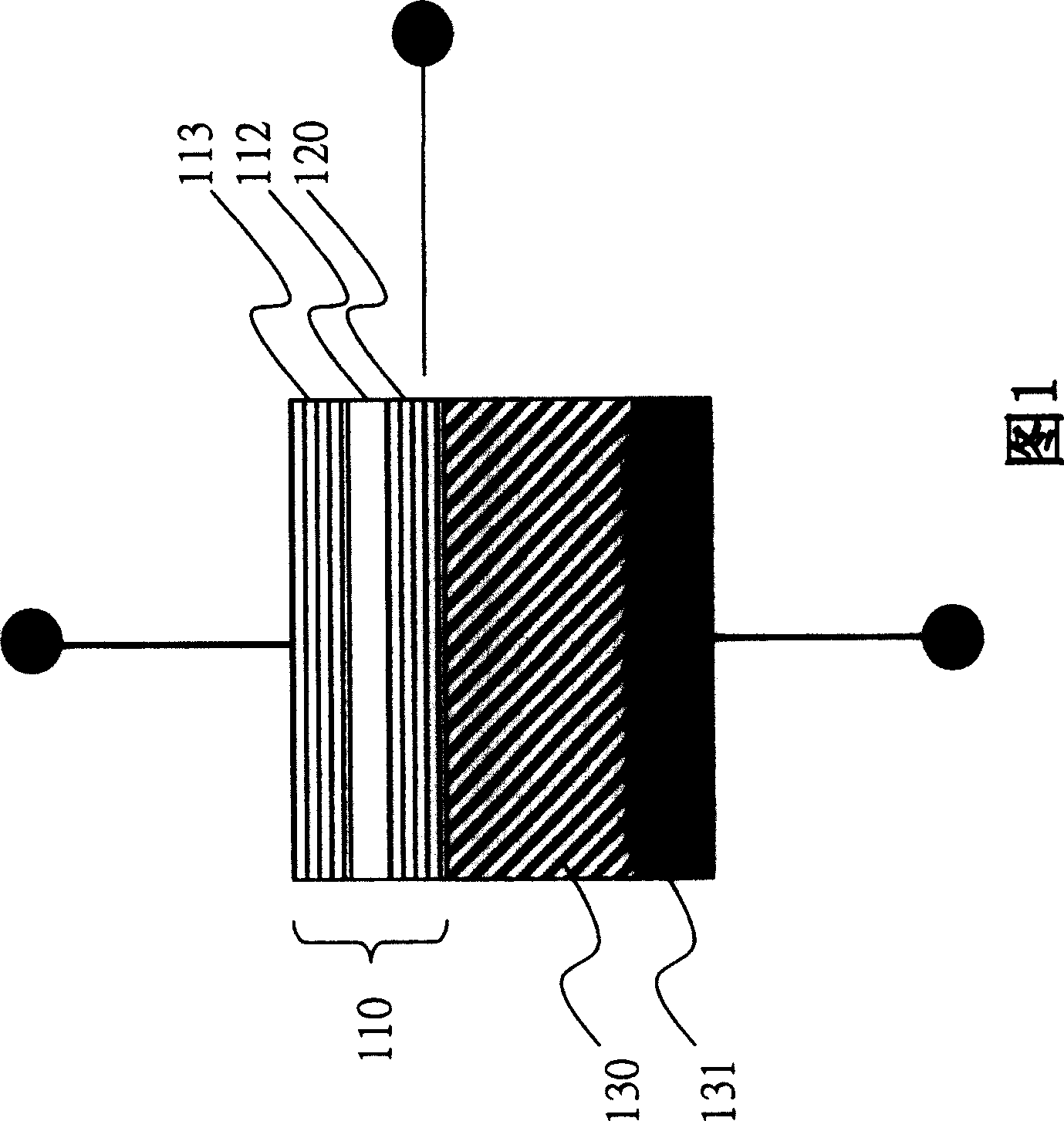
[0031] FIG. 1 is a schematic diagram of the structure of the magnetoresistive transistor of the first embodiment of the present invention, which proves that the structure of the present invention can indeed increase the change rate of the base current. In this structure, a current perpendicular to the planes (CPP) structure is formed by stacking the magnetoresistive component 110 , the passive component 130 and the ohmic contact layer 131 . The magnetoresistive component 110 is used as an emitter and a base, and the collector is a p-n diode with a pn junction, and the passive component 130 is formed on a silicon substrate as a collector; at the same time, the lower surface of the passive component 130 is plated with a titanium layer and The gold layer is used as the ohmic contact layer 131; the magnetoresistive component 110 is used as the emitter, which can provide different resistances with or without an external magnetic field. In the first embodiment, the magnetoresistive ...


PUM


Abstract

Structure of the transistor with magneto resistance is as following: subassembly of magneto resistance is as emitter; passive block is as collector; base electrode is connected between the emitter and the collector; the emitter is conducted to the collector electrically. Under control of external magnetic field, magnetic multilayer film in subassembly of magneto resistnace can generate two magnetic directions: parallel state and antiparallel state. Further, under fixed voltage, different magnitudes of input current of emitter are generated. Output current of base is changed as change of input current of emitter so as to be able to generate quite large rate of change of base electrode current.

Description

technical field [0001] The invention relates to a transistor, in particular to a magnetoresistance transistor using electron spin characteristics. Background technique [0002] Spin transistors are a new generation of electronic components that use the spin characteristics of electrons and the action of an external magnetic field to control the flow of current, thereby producing an effect similar to that of traditional transistors. Traditional components only use electronic charge as a control parameter, and the spin characteristics of electrons have two spin states: spin up and spin down. Therefore, components using electron spin characteristics will have more There are many control parameters, and the circuit design is more flexible. [0003] The currently developed spin transistor is a double-barrier spin transistor structure, which provides two potential barriers in the transistor, and combines the magnetoresistive components to use spin electrons in different magnetic ...

Claims


Application Information

Patent Timeline
Patent Type & Authority Patents(China)
IPC IPC(8): H01L41/12H01L29/72H01L43/00
Inventor 黄瀛文卢志权姚永德谢蓝青朱朝居黄得瑞
Owner IND TECH RES INST
Why Eureka
Try Eureka