Rock engaged combined pile and its construction method

A technology of combining piles and pile sections, which is applied in the direction of sheet pile walls, foundation structure engineering, construction, etc., can solve the problems of increased pile cap thickness, reduced bearing capacity, and increased construction cost, and achieves the improvement of single pile bearing capacity, contact The effect of increasing the area and improving the matching degree

Inactive Publication Date: 2009-07-01
LIJI ENG
View PDF3 Cites 2 Cited by
  • Summary
  • Abstract
  • Description
  • Claims
  • Application Information

AI Technical Summary

Problems solved by technology

The disadvantage of this is that the construction noise is large and the vibration is severe; the second is that the pile body is easily damaged or weakened under the violent and continuous impact of the piling hammer; the third is the ability of the squeezed soil to drive the pile to penetrate the hard soil layer Poor, when some piles of the foundation have to be located on the local hard soil layer, it is easy to cause uneven settlement of the building and tilt; Fourth, under the same bearing capacity, the self-weight of the prefabricated concrete pile is usually equal to that of the steel pile 2 to 3 times, the energy of the required pile hammer has been greatly increased, resulting in the inability of general piling machinery to drive the pile into the corresponding bearing layer; fifth, the piling must be driven in strict order, otherwise the pile driven in the later stage will "put the pile into the corresponding bearing layer". Squeeze away from the original position, because the soil extrusion stress of the piles driven in the early stage will not dissipate in a short time, which makes it difficult to drive the piles later, and has to be driven back, which delays the construction period
Construction costs also increase accordingly
[0005] 2. The shaped steel piles in the rock holes have not been specially processed, and their surface area has not been increased. The bonding force between the smooth surface and the grouting material is not ideal, thus requiring deeper rock holes and increasing the construction cost
When the grouting material is improperly configured to shrink or leave impurities, it will cause a weak link in the rock hole pile section, resulting in a decrease in bearing capacity
[0006] 3. Due to the high technical requirements for the production of H-shaped steel and the shortage of resources, it cannot be produced by ordinary manufacturers, so the cost of the steel pile body is generally higher than that of the reinforced concrete pile body
However, there are still many defects in this composite pile. For example, the composite pile must be provided with full-length steel bars and grouting in the pile body so as to bear tension and pressure together with the concrete pipe pile. The full-length steel bars generally exceed 12 meters and need to be connected and installed. Inconvenient, heavy on-site workload and high construction cost; the inner space of the concrete pipe pile is limited, the number of reinforcement bars is limited, its bearing capacity is limited, and the grouting pipe is easy to block or form large air bubbles, resulting in hidden engineering accidents; in order to To exert the bearing capacity of the full-length steel bar, it must be penetrated into the pile cap for at least one anchor length, resulting in an increase in the thickness of the pile cap

Method used


Image

  • Rock engaged combined pile and its construction method
  • Rock engaged combined pile and its construction method
  • Rock engaged combined pile and its construction method

Examples


no. 1 example

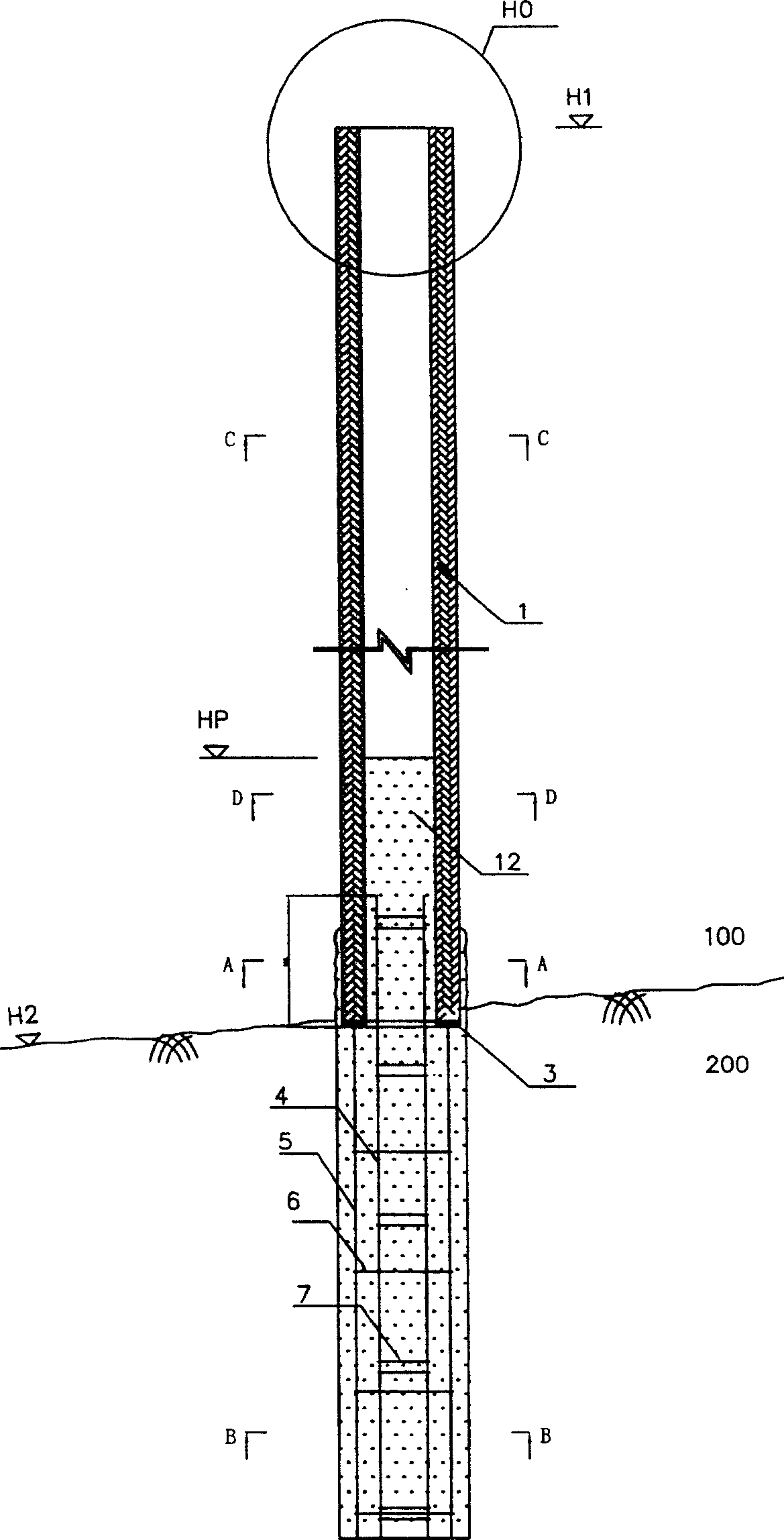
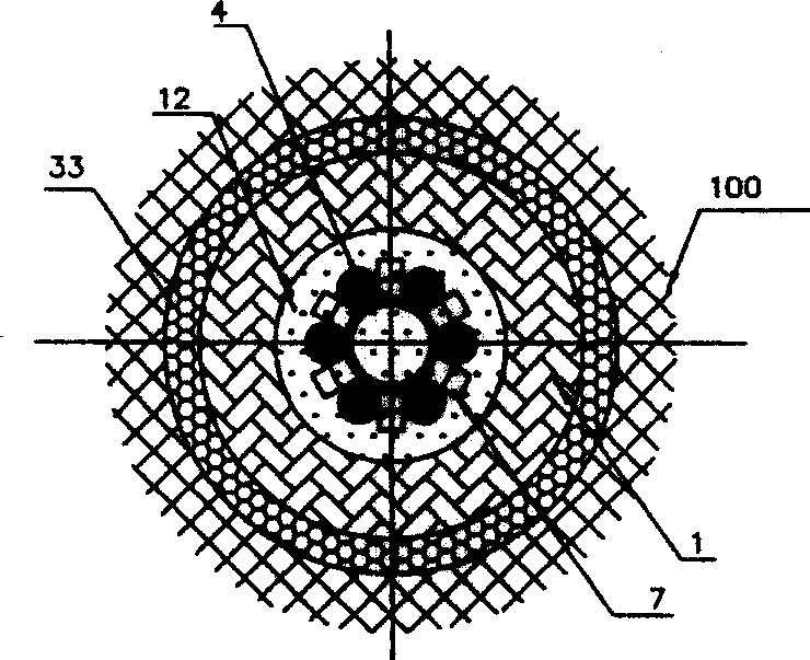
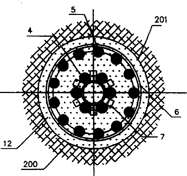
[0057] Such as figure 1 Shown is the whole pile sectional view of the first embodiment of the present invention (subclass 1 shown in the table). 100 in the figure is the soil layer, 200 is the stone layer, H1 is the design elevation of the pile head, H2 is the elevation of the rock top surface, H0 is the pile head according to the specific design, HA is the anchorage height of the steel bar, and HP is the grouting height according to the design requirements . The pile section in the soil layer is a concrete prefabricated casing pile 1, and the pile section in the rock hole uses an outer reinforcement cage 5 and an inner reinforcement cage 4 to form a member with a large surface area and fully contacted with the grouting material 12. 6 in the figure is the stirrup of the outer cage, 7 is the vertical member of the inner cage, and 3 is a flange made of annular steel plate, which is connected to the outer reinforcement cage 5 and the prefabricated cage by welding (including butt...

no. 2 example

[0062] Figure 4 It is a sectional view of the whole pile of the second embodiment of the combined pile of the present invention, which combines subclass 1 and subclass 2 shown in the table. The second embodiment is composed of the hollow prefabricated pipe 1 in the soil layer 100, the cast-in-place pile body formed by adding the section steel 21 in the stone layer 200, and the inner reinforcement cage 4 grouted. The pile sections in the soil layer 100 are the same as those in the first embodiment, and will not be repeated here. The pile section in the stone layer 200 is made of section steel 21 and optionally provided with an inner reinforcement cage 4 according to the specific design. At the same time, an annular connecting plate 3 and a selective reinforcement member 13 are used, so that the load from the upper hollow pipe 1 can be transmitted smoothly steel 21, so the role of the reinforcing member 13 is to expand the contact surface between the steel 21 and the connectin...

no. 3 example

[0066] Figure 7 Shown is the whole pile sectional view of the third embodiment of the composite pile of the present invention. The third embodiment shows subclass 3 in the table; it can be seen that the pile body in the soil layer 100 of this embodiment is the same as that of the first two embodiments, that is, the grout 12 is not poured to the top of the pipe pile member 1 . And the pile body being in the rock hole 201 is a prefabricated reinforced concrete member, which is a prefabricated multifaceted pipe 14 in the shape of a truncated cone with a small head downward, in fact it can be designed as a pipe or column of any shape with a concave-convex surface Body, the purpose is to improve the bonding force between it and the filling material. The center of the tapered prefabricated pipe 14 has a stepped hole through both ends, and the top of the stepped hole is a large diameter hole to reduce the transport weight of the prefabricated part and strengthen the integrity of t...


PUM


Abstract

A rock-socketed composite pile, comprising a pile segment located in the soil layer and a pile segment located in the rock layer, the pile segment in the soil layer and the pile segment in the rock layer are connected together, and the rock-socketed composite pile also includes filling Material. Wherein, the pile section in the soil layer of the present invention can be selected from two components of prefabricated (including prestressed) reinforced concrete casing or steel pipe filled with filling materials, and steel piles wrapped with filling materials. The pile section in the rock formation of the present invention can be selected from one or any combination of these three components: reinforcement cage, steel member and prefabricated reinforced concrete member, and the filling material is filled in the rock formation hole. The pile body in the rock hole spreads the load to the depth of the rock formation by the bonding force between the filling material and the wall of the rock hole. Since the contact area between the pile body and the filling material is larger than that of a pile with a common shape, it can fully provide anchoring force.

Description

technical field [0001] The invention relates to a pile as a deep foundation of a building, especially a composite pile that relies on grouting materials, prefabricated piles, and the cohesive force of the inner wall of a rock hole to gradually spread the load to the bearing rock layer along the vertical direction; The contact area and mechanical bite force between the prefabricated component and the grouting material in the rock hole enable the rock hole to provide the rock-socketed composite pile with the maximum bearing capacity and its construction method. Background technique [0002] The prefabricated piles used in the general pile foundation are all connected with the prefabricated reinforced concrete piles or section steel piles one by one on site with a pile driver, and the soil is squeezed into the design depth. The pile head load is supported by the friction between the pile body and the surrounding soil and the bearing capacity of the bearing layer at the bottom o...

Claims


Application Information

Patent Timeline
Patent Type & Authority Patents(China)
IPC IPC(8): E02D5/48E02D5/50
Inventor 张向东袁炎波
Owner LIJI ENG
Why Eureka
Try Eureka