Turning holder with a convenient easy-adjustable movable loading plate

A technology of bearing plate and turnover frame, which is applied in the field of turnover frame, can solve the problems of inability to realize automatic control adjustment, low adjustment accuracy, low adjustment efficiency, etc., and achieve the effect of compact structure, wide power source and smooth movement

Inactive Publication Date: 2009-07-22
张彦勤
View PDF7 Cites 0 Cited by
  • Summary
  • Abstract
  • Description
  • Claims
  • Application Information

AI Technical Summary

Problems solved by technology

As disclosed in the Chinese patent document CN2539679, a horizontal turnover vehicle for horizontally storing PCB boards uses a screw and nut structure. When the turnover frame with this structure needs to adjust the distance between the bearing plates, it needs to be used first. The wrench loosens the upper and lower nuts on the screw rod, and then adjusts, which is very troublesome to adjust. After the adjustment, the nuts need to be tightened again. When it is used again, it needs to be adjusted again in the same way, which is labor-intensive and time-consuming.
Moreover, the turnover frame of this structure can only be adjusted manually, which not only has low adjustment efficiency, but also has low adjustment accuracy. In addition, this type of turnover vehicle cannot realize automatic control and adjustment on-line with external equipment

Method used


Image

  • Turning holder with a convenient easy-adjustable movable loading plate
  • Turning holder with a convenient easy-adjustable movable loading plate
  • Turning holder with a convenient easy-adjustable movable loading plate

Examples


Embodiment Construction

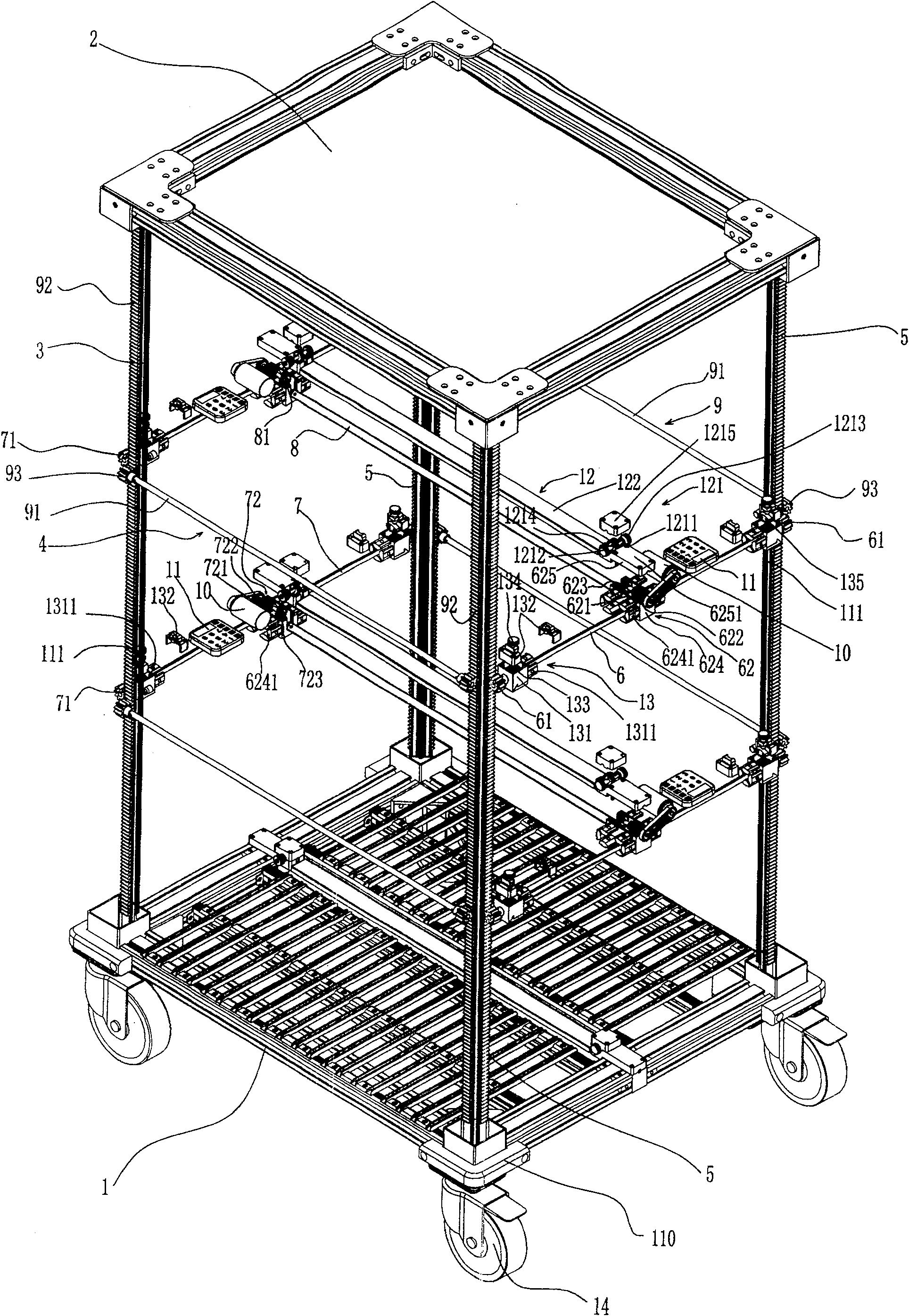
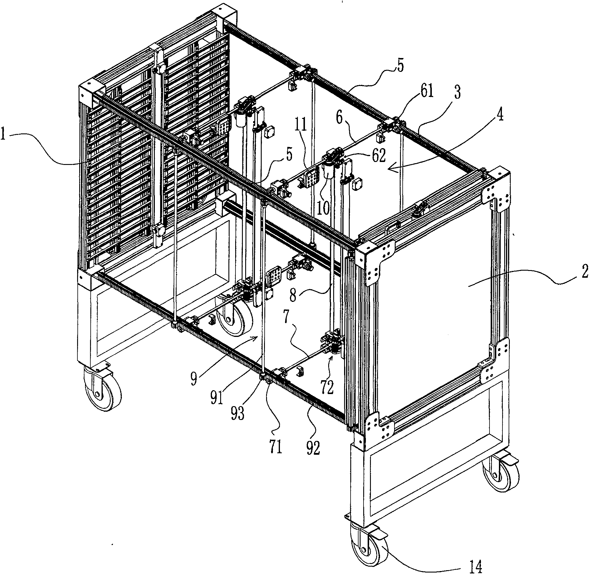
[0046] The present invention will be further described below in conjunction with accompanying drawing:

illustration:

[0047] 1. Lower panel;

[0048]11. Automatic control device; 111. Position sensor; 112. Scale; 113. Position indicating arrow;

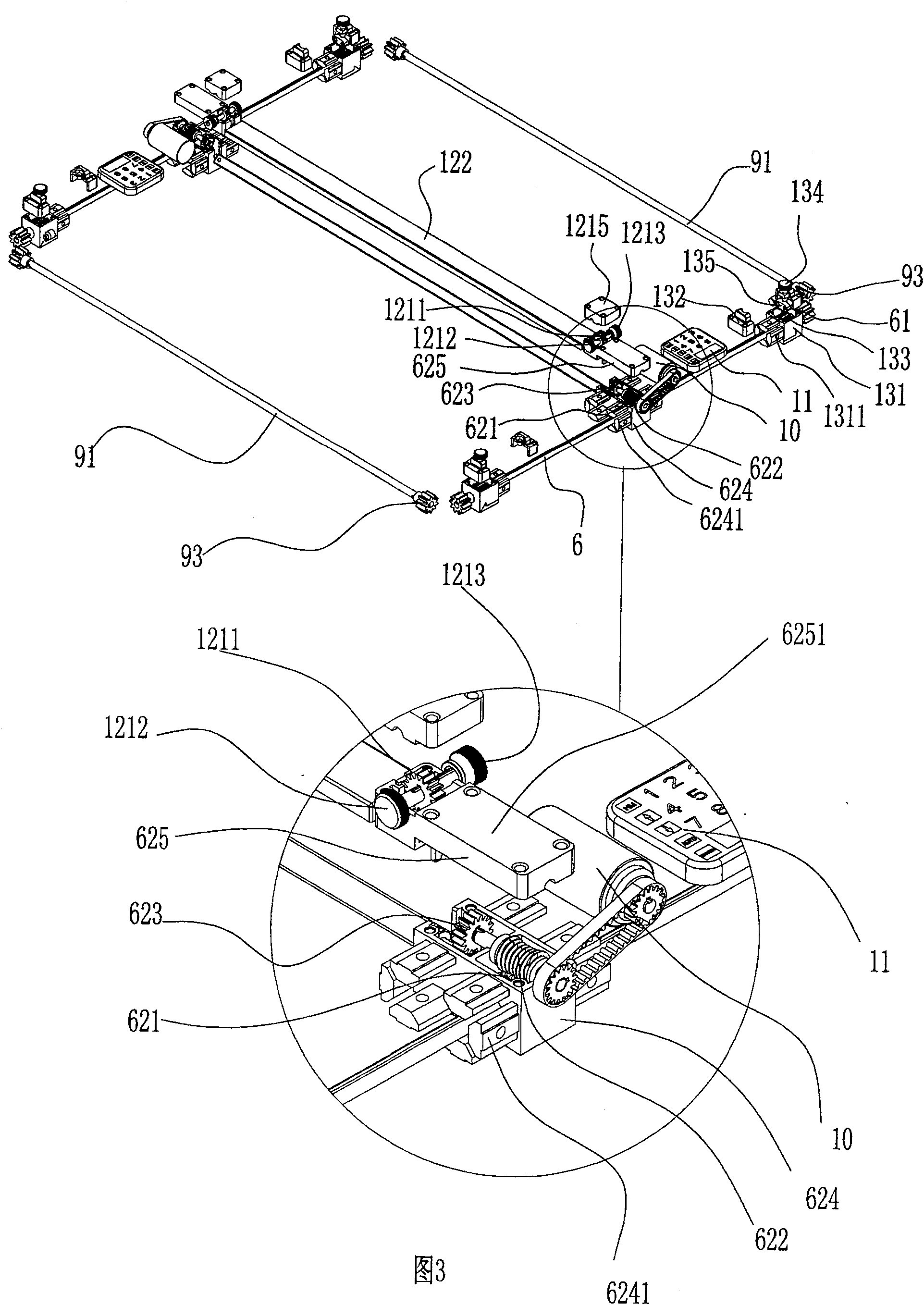
[0049] 12, stop rod mechanism; 121, stop rod lifting mechanism; 1211, gear; 1212, knurled screw rod; 1213, positioning knurled nut 1214, movable rack; 1215, lifting mechanism cover; 122, stop rod;

[0050] 13. Safety lock mechanism; 131. Safety lock gear box; 1311. Plug; 1312. End face of safety lock gear box; 1313. Safety lock gear box hole; 132. Safety lock gear box cover; 133. Safety lock gear; 134. Safety Knurled screw rod; 135, tooth fork; 136, nut cover; 137, nut;

[0051] 14. Casters;

[0052] 2. Upper panel;

[0053] 3. Connecting piece; 30. Hand wheel;

[0054] 4. Movable bearing plate; 41. Laminate beam; 411. Hole; 412. End face; 413. Notch;

[0055] 42. Flat deck beams; 43. Corner connectors;

[0056] 5. Rack;

...


PUM


Abstract

A turnover frame for a convenient and easy-to-adjust movable bearing plate, comprising a vehicle frame and at least one movable bearing plate, the movable bearing plate includes a driving part of the movable bearing plate and a bearing plate part, and the structure of the driving part is: Each connecting piece is provided with a tooth rack, and the tooth direction of the tooth racks on the connecting piece on the same side is the same; a transmission shaft is respectively provided between the two tooth racks on the same side, and the two ends of the transmission shaft are respectively Each is provided with a gear, and the gears are meshed with their corresponding racks; a worm gear mechanism is provided on the transmission shaft, and the worm gear in the worm gear mechanism is fixedly connected to the transmission shaft coaxially; the movable bearing The disc portion is arranged on at least the driving drive shaft and the driven drive shaft. The invention has the advantages of high adjustment efficiency, accurate adjustment and positioning and wide power sources.

Description

technical field [0001] The invention relates to a turnover frame for indoor and outdoor utensil turnover, in particular to a turnover frame which can conveniently and easily adjust a movable bearing plate. Background technique [0002] Existing material turnover racks, especially those used for circuit boards, are generally divided into two types: vertical or horizontal. No matter whether it is a vertical or horizontal turnover rack, due to the The size is different, and the distance between the bearing plates needs to be adjusted frequently. Because the existing turnover frame is used to adjust the structure of the pitch, it is the structure of the screw rod and the nut that is adopted, and the vertical turnover vehicle is as disclosed in the Chinese patent document CN2471669 and a kind of antistatic PCB board turnover vehicle disclosed in the Chinese patent document CN2511568. Disclosed is an antistatic plug-in turnover car. As disclosed in the Chinese patent document CN...

Claims


Application Information

Patent Timeline
Patent Type & Authority Patents(China)
IPC IPC(8): B62B3/02
Inventor 张彦勤
Owner 张彦勤
Why Eureka
Try Eureka