
Pressure sensor comprising an elastic sensor layer with a microstructured surface

一种压力传感器、传感层的技术,应用在仪器、测量力、测量装置等方向,能够解决难检验传感器、反应阈值相同量级偏移等问题

Inactive Publication Date: 2009-07-22
IEE INT ELECTRONICS & ENG SA
View PDF4 Cites 0 Cited by
  • Summary
  • Abstract
  • Description
  • Claims
  • Application Information

AI Technical Summary

Problems solved by technology

Indeed, even very small changes in the cell structure, e.g., through deformation of the membrane, lead to a shift in the turn-on point of the same order of magnitude as the desired response threshold
In addition, random variations in the distribution of contact points in the semiconductor layer make it difficult to examine the behavior of the sensor above its response threshold

Method used


Image

  • Pressure sensor comprising an elastic sensor layer with a microstructured surface
  • Pressure sensor comprising an elastic sensor layer with a microstructured surface
  • Pressure sensor comprising an elastic sensor layer with a microstructured surface

Examples


Embodiment Construction

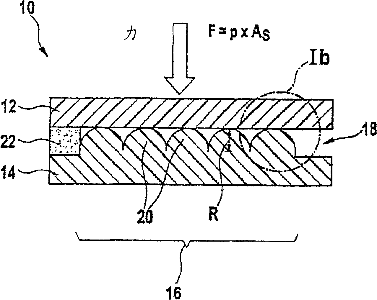
[0030] The present invention relates to pressure sensors based on elastic-mechanical deformation of microstructured surfaces. Figure 1a The structure of such a pressure sensor 10 is schematically shown. The sensor 10 basically comprises a first sensing layer 12 and a second sensing layer 14 of elastic and resistive material, each typically coated on a carrier foil (polymer foil) (not shown). Sensing layers 12 and 14 are arranged opposite each other so that a contact area is formed between them in active area 16 of pressure sensor 10 .

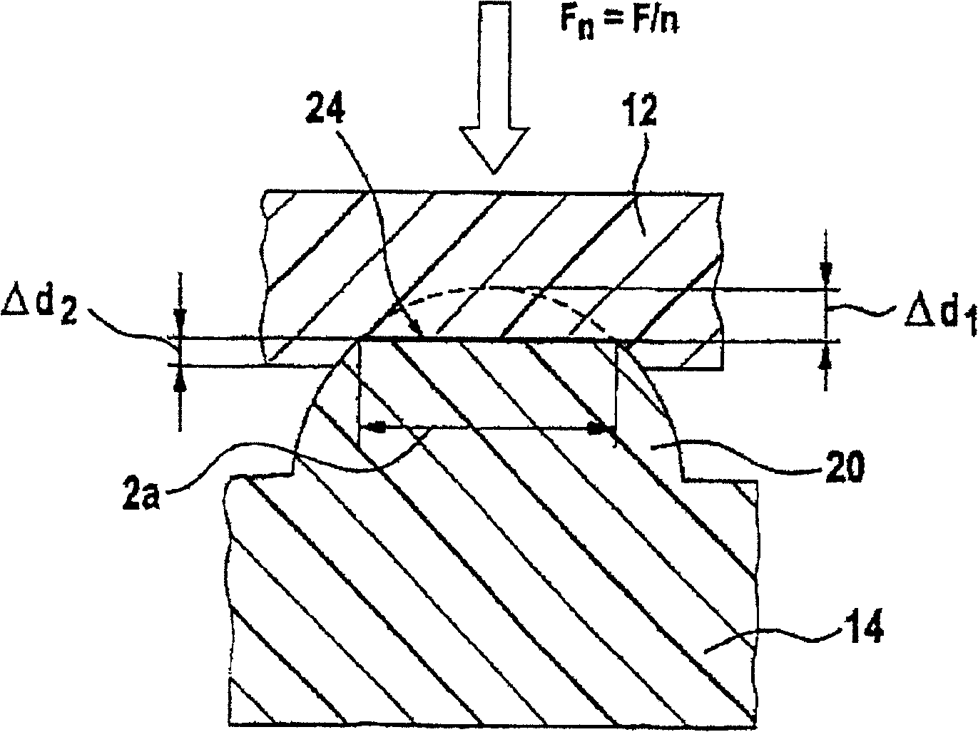
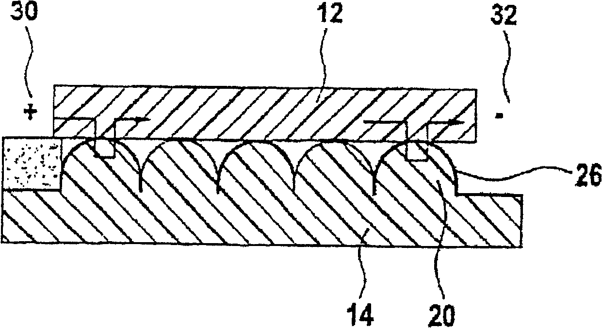
[0031] The second sensor layer 14 has a microstructured surface 18 in the region of the active region 16 of the pressure sensor 10 , which has a predetermined structure 20 of elastic material formed therein. Figure 1a A typical embodiment of such a pressure-sensitive microstructure 18 is shown. To this end, the second sensing layer 14 comprises a clearly defined topography in the active area 16 , which takes the form of a spherical structure ...


PUM


Abstract

A pressure sensor has first (12) and second (14) sensor layers that are made from flexible, resistive material and are each applied to a polymer foil. A spacer (22) is coated with an adhesive. The second sensor layer has a micro-structured surface with spherical structures (20) in an active zone (16). The radius (R) of the spherical structures is 50 mum and the compression path 10 mum.

Description

technical field [0001] The present invention relates to a pressure sensor, in particular to a pressure sensor based on micromachines. Background technique [0002] The field of application of pressure sensors for detecting force or pressure applied to surfaces has grown significantly in recent years. For most of these applications, the main requirement of a pressure sensor is that the pressure sensor can be manufactured at a reasonable cost. Therefore, foil-type pressure sensors in particular are widely spread. [0003] This type of pressure sensor is economical to manufacture and its applications are diverse, which is described, for example, in US-A 4314227 . The foil-type pressure sensor described in this document is equipped with two support plates kept at a certain distance apart by a divider. At least one of the support plates is elastic in configuration such that when a force is applied to the sensor, the elastic support plate can be pressed against the other suppor...

Claims


Application Information

Patent Timeline
Patent Type & Authority Patents(China)
IPC IPC(8): G01L1/20
CPCG01L1/205G01L1/20
Inventor 沃纳·比克阿洛伊斯·基尔希阿兰·舒马赫阿洛伊斯·斯库斯
Owner IEE INT ELECTRONICS & ENG SA
Learn More