Solar module rear side encapsulation element and solar module

a solar module and encapsulation element technology, applied in photovoltaics, electrical equipment, applications, etc., can solve the problems of increased uv exposure, limited suitability of solar modules for desert use, and inability to protect solar modules sufficiently long, so as to achieve more cost-effective effects

Inactive Publication Date: 2016-03-03
HANWHA Q CELLS
View PDF2 Cites 0 Cited by
  • Summary
  • Abstract
  • Description
  • Claims
  • Application Information

AI Technical Summary

Benefits of technology

[0029]Furthermore, it is possible to thermally connect the at least one protective layer especially the metal protective layer to a junction box of the solar module. In this manner the heat developing generally in the semiconductor diodes provided in the junction boxes can be dissipated and distributed in a better manner via the back surface of the solar module. Also, it is possible to integrate in the solar module rear side encap

Problems solved by technology

Although it has an improved resistance to hydrolysis and good electro-isolating properties, it is not able to protect a solar module sufficiently long in a weather-resistant manner in regions having many dust storms and sandstorms and increased UV exposure.
Thus, such a solar module is of limited suitability for use in a desert region.
Especially in desert region

Method used


Image

  • Solar module rear side encapsulation element and solar module
  • Solar module rear side encapsulation element and solar module

Examples


first embodiment

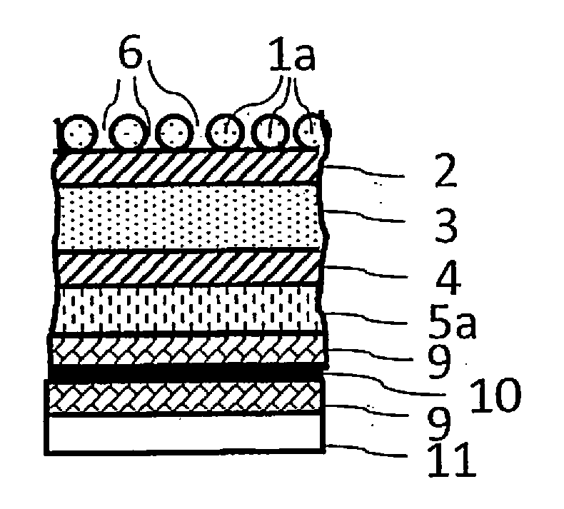
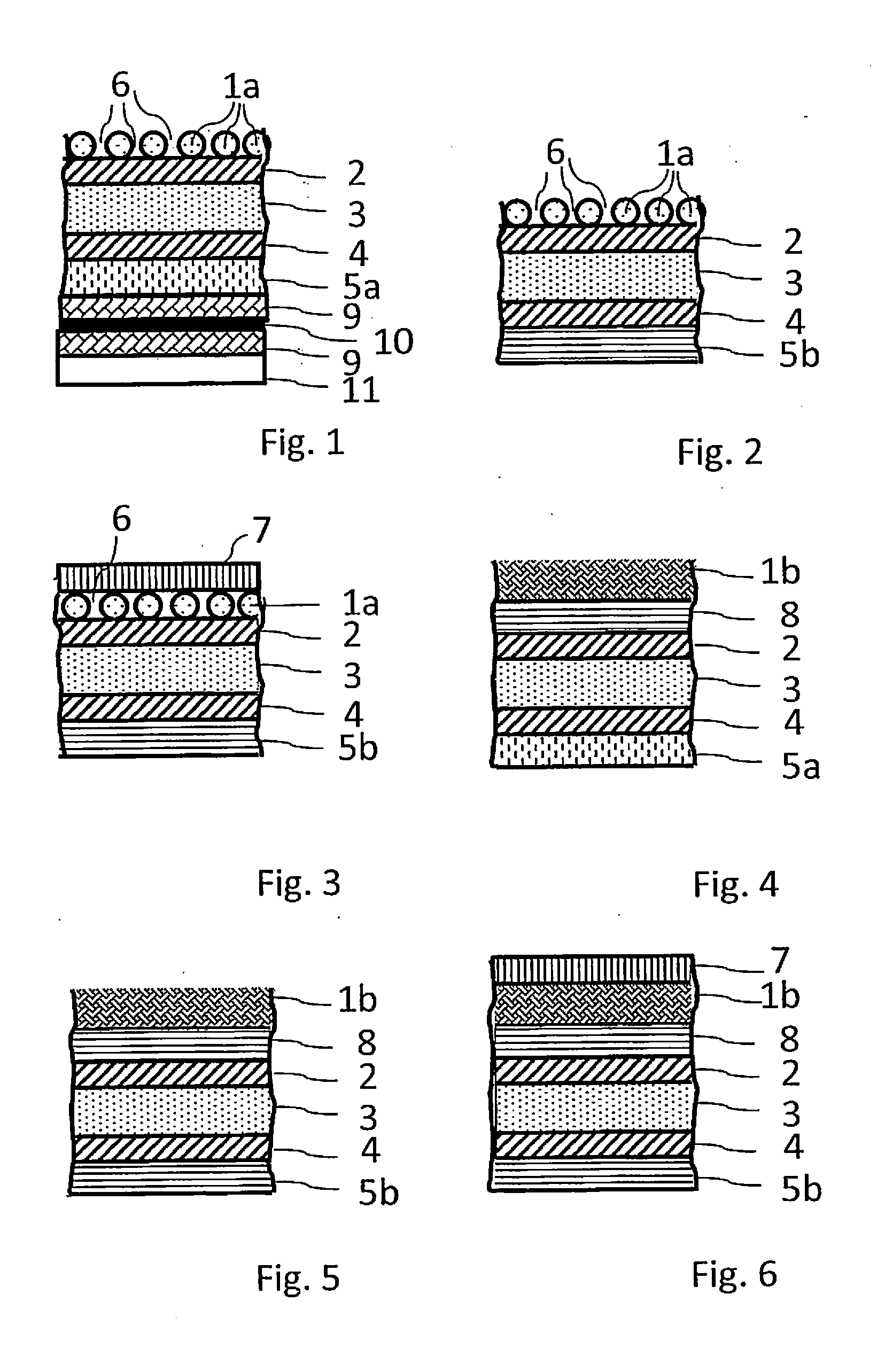
[0038]FIG. 1 shows a schematic and non-scaled partial cross-sectional view of a solar module having a solar module rear side encapsulation element according to a The solar module has a front side encapsulation element 11, the front side thereof being a light-incident side of the solar module and an encapsulation material 9 being arranged on the rear side thereof. Furthermore, the solar module comprises solar cell strings 10 arranged on the rear side of the front side encapsulation element 11 that are connected to each other and embedded in the encapsulation material 9 so that both the side of the solar cell string 10 facing to the front side encapsulation element 11 and the side of the solar cell string 10 facing away from the front side encapsulation element 11 are surrounded by the encapsulation material 9. Furthermore, the solar module has a solar module rear side encapsulation element arranged on the side of the solar cell string 10 facing away from the front side encapsulation...

second embodiment

[0040]FIG. 2 shows a schematic and non-scaled partial cross-sectional view of a solar module rear side encapsulation element according to a The solar module rear side encapsulation element shown in FIG. 2 corresponds to the solar module rear side encapsulation element shown in FIG. 1 with the difference that it comprises a more cost-efficient polyolefin film 5b made of polyethylene instead of the polyvinyl fluoride film 5a.

third embodiment

[0041]FIG. 3 shows a schematic and non-scaled partial cross-sectional view of a solar module rear side encapsulation element according to a The solar module rear side encapsulation element shown in FIG. 3 corresponds to the solar module rear side encapsulation element shown in FIG. 2 with the difference that the protective layer 1a is laminated. A polymer foil 7 is arranged on the protective layer 1a so that the polymer foil 7 is the outer face of the rear side encapsulation element and the solar module not shown completely. Alternatively, the outermost layer can be also formed as sacrificial layer made of a non-polymeric and non-metallic material.


PUM

PropertyMeasurementUnit
Fractionaaaaaaaaaa
Fractionaaaaaaaaaa
Fractionaaaaaaaaaa

Abstract

A solar module rear side encapsulation element having a laminate-type layer construction having at least one polymer plate or polymer foil having a laminate surface. The laminate-type layer construction has at least one protective layer having layer openings. The protective layer covers at least 70% of the laminate surface by a covering area, and due to the layer openings at least 15% and maximum 99.9% of the regions of the solar module rear side encapsulation element lying under the protective layer are covered in the covering area, and the protective layer is formed as a structure made of threads, thus being open to diffusion.

Description

PRIORITY CLAIM[0001]The present application claims priority to German Patent Application No. 102014112650.5, filed on Sep. 3, 2014, which said application is incorporated by reference in its entirety herein.FIELD OF THE INVENTION[0002]The present invention relates a solar module rear side encapsulation element and a solar module comprising this solar module rear side encapsulation element.BACKGROUND OF THE INVENTION[0003]A solar module rear side encapsulation element should be so weather resistant that a sufficient isolation of the solar cells of the solar module to weather exists even after decades in outdoor use. Generally, this is ensured by laminates made of polyvinyl fluoride (PVF) (e.g., Tedlar®, DuPont, USA, Wilmington) and polyethylene terephthalate (PET), polyethylene terephthalate being generally arranged as an isolating central film between two Tedlar® films and optionally further adhesive layers. Also, layers made of polyolefins, polyamide or other polymers can be used. ...

Claims


Application Information

Patent Timeline
IPC IPC(8): H01L31/048B32B5/02B32B27/12B32B27/32B32B27/36
CPCH01L31/048B32B5/028B32B27/12B32B2262/103B32B27/32B32B2457/12B32B27/36B32B15/08H01L31/0481B32B3/14B32B5/024B32B5/026B32B7/12B32B27/08B32B27/304B32B2307/712H01L31/049Y02E10/50
Inventor SCHURADE, MAXIMILIANTRAGER, MARKUSMETTE, MICHAEL
Owner HANWHA Q CELLS
Why Eureka
Try Eureka