Fuel jetting valve dispatching structure of V-type two-cylinder engine

A fuel injection valve and engine technology, applied in fuel injection devices, low-pressure fuel injection, low-pressure fuel injection, etc., can solve problems such as not meeting the intake efficiency

Inactive Publication Date: 2009-07-29
HONDA MOTOR CO LTD
View PDF5 Cites 0 Cited by
  • Summary
  • Abstract
  • Description
  • Claims
  • Application Information

AI Technical Summary

Problems solved by technology

However, such a configuration relationship does not conform to the characteristics of intake efficiency

Method used


Image

  • Fuel jetting valve dispatching structure of V-type two-cylinder engine
  • Fuel jetting valve dispatching structure of V-type two-cylinder engine
  • Fuel jetting valve dispatching structure of V-type two-cylinder engine

Examples


Embodiment Construction

[0016] Embodiments of the present invention will be described below with reference to the drawings. The drawings are viewed in the direction of the markings.

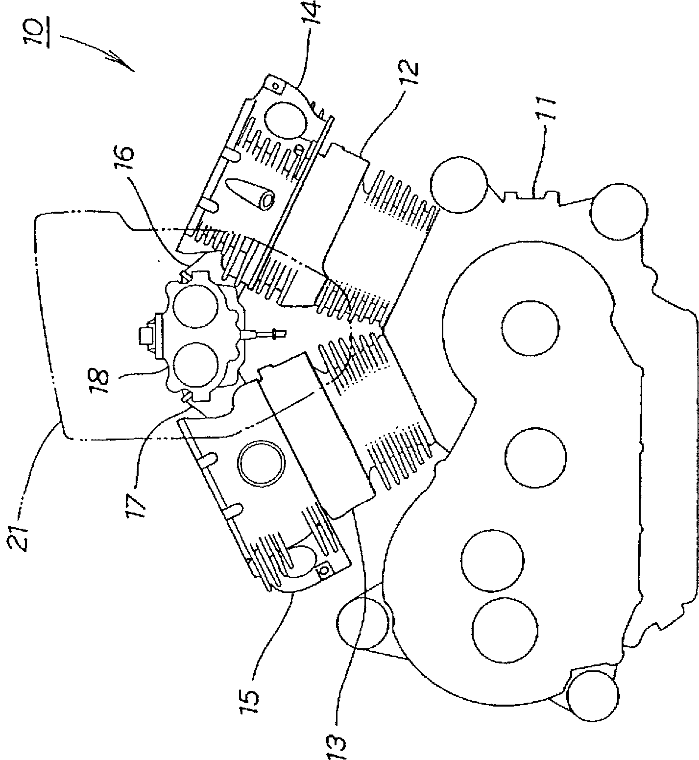
[0017] figure 1 It is a side view of the engine adopting the structure of the fuel injection valve of the present invention. The engine 10 is a V-type 2-cylinder engine. A first cylinder block 12 and a second cylinder block 13 are installed on the top of the crankcase 11, and a first cylinder head 14 is installed on the top of these first and second cylinder blocks 12 and 13, respectively. and the second cylinder head 15, on these first and second cylinder heads 14 and 15, a throttle body 18 for 2 cylinders is installed through the first and second intake manifolds 16 and 17, and the throttle body 18 Air filter 21 is installed on it.

[0018] The engine 10 is a V-type engine whose cylinder pinch angle is less than 90°. Since it is difficult to arrange the throttle body 18 between the first and second cylinder heads ...


PUM


Abstract

The present invention provides a fuel injection valve arrangement structure for a V-type 2-cylinder engine. The cylinders are offset from each other in the direction of the crankshaft, and throttle bodies for 2 cylinders are arranged on one side of the engine in the direction of the crankshaft. A 2-way injection type fuel injection valve is provided. Installed in the intake manifold and inject fuel into the combustion chamber equipped with two intake holes arranged along the camshaft; relative to the engine centerline, the first combustion chamber is arranged on the side of the throttle body, and the second combustion chamber is arranged On the side opposite to the throttle body; the centerline of the outlet of the first intake manifold and the centerline of the outlet of the second intake manifold are respectively relative to the centerline of the first combustion chamber and the second combustion chamber to the engine centerline Side offset; the axis of the first fuel injection valve and the axis of the second fuel injection valve are respectively offset to the center line of the engine relative to the center line of the first combustion chamber and the second combustion chamber, relative to the first intake manifold The centerline of the outlet of the second intake manifold is offset to the side opposite to the centerline of the engine.

Description

technical field [0001] The present invention relates to an arrangement structure of an engine fuel injection valve suitable for improving engine performance regardless of the arrangement of engine components. Background technique [0002] Figure 4 It is a sectional view showing the fuel injection state of a conventional engine. An intake manifold 101 is attached to the cylinder head 100, a fuel injection valve 102 is attached to the intake manifold 101, and fuel 104 is injected from the fuel injection valve 102 to an intake passage 103 provided on the cylinder head 100. Inside. 105 is the opening of the intake passage 103 toward the fuel chamber 106 (i.e., the intake side valve seat), 107 is the intake valve for opening and closing the opening 105, 108 is the exhaust passage, and 111 is the direction of the exhaust passage 108. The opening of the fuel chamber 106 (that is, the valve seat on the exhaust side), 112 is an exhaust valve that opens and closes the opening 111 ....

Claims


Application Information

Patent Timeline
Patent Type & Authority Patents(China)
IPC IPC(8): F02M39/00F02M61/14F02B23/08F02B61/02F02B75/22F02F1/24F02F1/42F02M69/00F02M69/04
CPCF02F1/242F02B2275/18F02F1/4214F02B61/02F02M69/045F02M69/044F02B75/22
Inventor 赤城贵乾博笃
Owner HONDA MOTOR CO LTD
Why Eureka
Try Eureka