Manufacturing method of burner fire lid

A manufacturing method and burner technology, applied in the direction of combustion methods, burners, gas fuel burners, etc., can solve the problems of high environmental pollution, increased production costs, and inability to align, and achieve simple processing methods, low production costs, non-slip effect

Inactive Publication Date: 2009-07-29
周建基
View PDF8 Cites 0 Cited by
  • Summary
  • Abstract
  • Description
  • Claims
  • Application Information

AI Technical Summary

Problems solved by technology

[0002] Existing household gas cooker, the fire hole direction on its burner fire cover is on the radial direction of fire hole circle, and the plane direction of fire hole and fire hole circle is parallel, the combustion of the gas that comes out from fire hole like this The cooking utensils on the gas stove cannot be aligned, and the combustion of the gas is not sufficient, which reduces the combustion utilization rate of the gas, and the waste gas produced by the combustion is more, causing more pollution to the environment. After the cover has been improved, it has applied for a structural patent in another case, such as Figure 1-4 As shown, its structural feature is that the fire hole direction of the fire cover forms a certain included angle α with the radial direction of the fire hole ring; at the same time, the fire hole also forms a certain included angle β with the plane direction after being inclined from bottom to top
The processing method of manufacturing common fire cover all the time is to carry out machining after forging and pressing, and then drill or cut grooves on the outer edge or the upper surface of the fire cover. For a new type of burner fire cover, when processing the fire hole, it is necessary to form an included angle α with the radial direction of the fire hole ring, and to form an included angle β between the fire hole and the plane direction, which will greatly increase the difficulty of drilling, and It is easy to drill the fire hole and make the whole fire cover useless, which greatly increases the production cost

Method used


Image

  • Manufacturing method of burner fire lid
  • Manufacturing method of burner fire lid
  • Manufacturing method of burner fire lid

Examples


Embodiment Construction

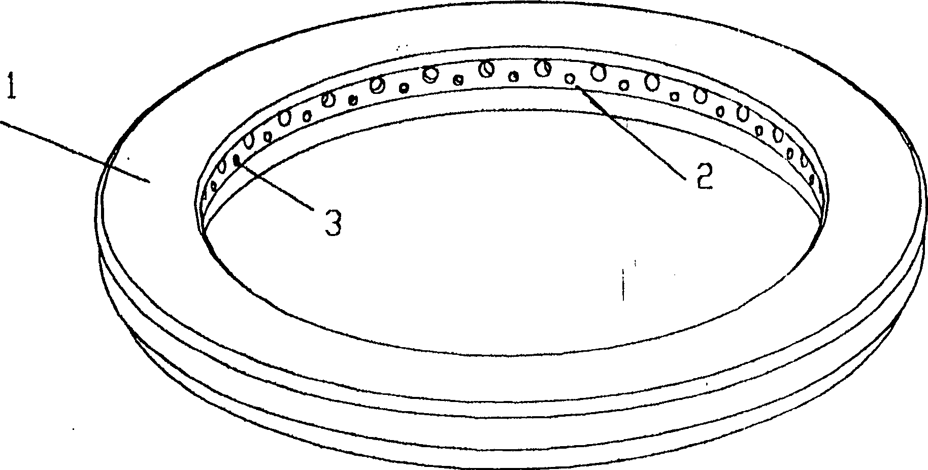
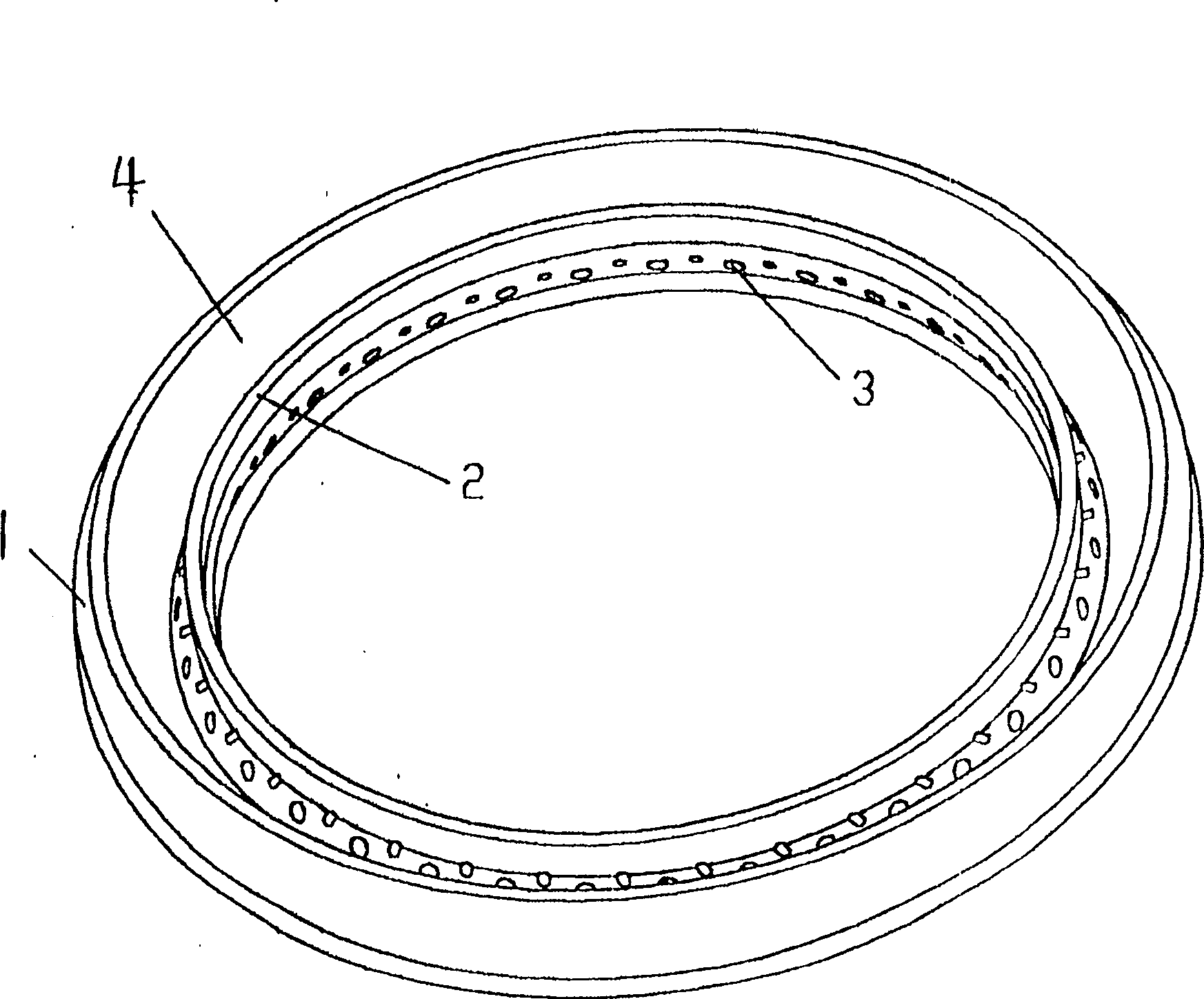
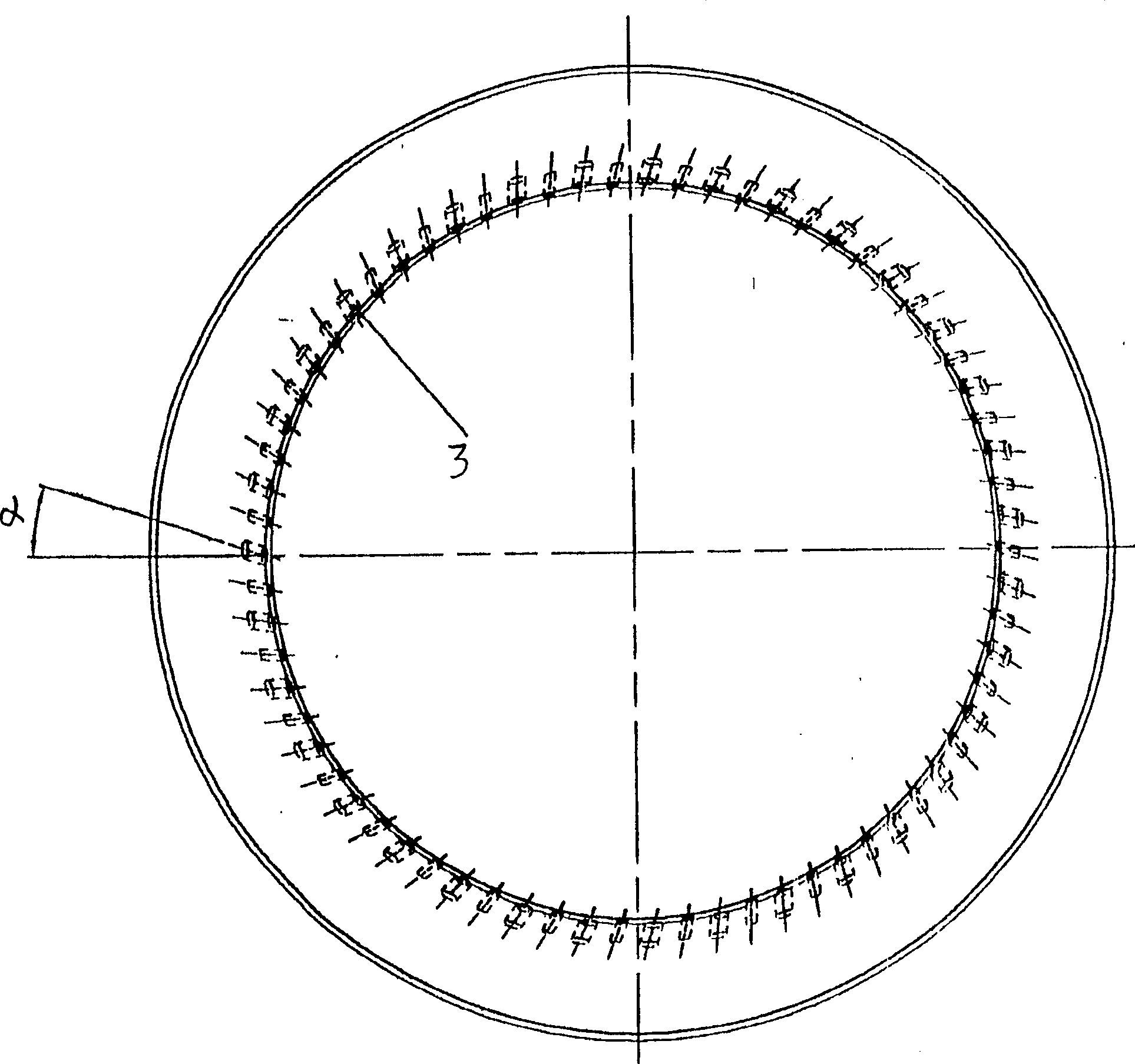
[0022] A kind of burner fire cover produced by the present invention, it comprises fire cover seat 1, is provided with gas channel 4 under fire cover seat 1, has on the fire hole circle 2 of described fire cover seat 1 inner side and this The fire hole 3 that gas channel 2 communicates, in order to make the gas combustion that comes out from fire hole 3 fully, reduce the pollution to environment, the direction of fire hole 3 and the radial direction of this fire hole ring 2 are set to certain angle α ( Such as image 3 shown), and at the same time make the fire hole 3 inclined from bottom to top and form a certain angle β with the plane direction (such as Figure 4 Show). In this way, the firepower after the combustion of the gas can be concentrated and just aligned with the cooking utensils on the burning range, and the combustion utilization rate of the gas can be improved. Usually, the angle α formed between the fire hole 3 and the radial direction of the fire hole ring 2...


PUM


Abstract

A method for manufacturing a burner cap, comprising the steps of: A, forging and forming, simultaneously forging a circle of evenly distributed helical teeth on the upper side of the inner circle of the fire cap, the drilling surface of the helical teeth is in contact with the fire cap An included angle α is formed between the radial directions of the inner circle, and an included angle β is also formed between the vertical surface of the fire hole at the root of the helical tooth and the vertical direction; B. Drilling the fire hole: use a clamp to clamp the fire cover, Make the drill bit stuck between the drilling surface of the helical tooth and the vertical surface of the fire hole at the root of the helical tooth to drill the hole, and make the vertical surface of the fire hole just perpendicular to the drill bit, and then start drilling the fire hole. After drilling a fire hole, rotate the fixture through the indexing plate on the fixture and drive the fire cover to rotate at the same time, so that the vertical surface of the fire hole of the next helical tooth is perpendicular to the drill bit, and then drill the drilling surface of the helical tooth and the helical tooth The fire holes between the vertical planes of the fire holes at the root, all the fire holes are drilled in this way; C, the helical teeth on the upper side of the inner circle of the fire cover are removed by car. The processing method of the invention is simple and the production cost is low.

Description

【Technical field】 [0001] The invention relates to a burner, in particular to a method for manufacturing a fire cover on the burner. 【Background technique】 [0002] Existing household gas cooker, the fire hole direction on its burner fire cover is on the radial direction of fire hole circle, and the plane direction of fire hole and fire hole circle is parallel, the combustion of the gas that comes out from fire hole like this The cooking utensils on the gas stove cannot be aligned, and the combustion of the gas is not sufficient, which reduces the combustion utilization rate of the gas, and the waste gas produced by the combustion is more, causing more pollution to the environment. After the cover has been improved, another structural patent has been applied for, such as Figure 1-4 As shown, its structural feature is that the fire hole direction of the fire cover forms a certain included angle α with the radial direction of the fire hole ring; at the same time, the fire hole...

Claims


Application Information

Patent Timeline
Patent Type & Authority Patents(China)
IPC IPC(8): F23D14/46
Inventor 周建基
Owner 周建基
Why Eureka
Try Eureka