
High energy pulsed spin plasma perforation method

A plasma and high-energy pulse technology, applied in the field of plasma perforation, can solve the problems of reducing oil and gas well production and production efficiency, decreasing rock permeability, and decreasing the connectivity between reservoir and wellbore, so as to improve production efficiency and total production. , the effect of improving connectivity

Active Publication Date: 2022-05-24
CHINA UNIV OF PETROLEUM (EAST CHINA)
View PDF7 Cites 0 Cited by
  • Summary
  • Abstract
  • Description
  • Claims
  • Application Information

AI Technical Summary

Problems solved by technology

However, the existing perforating bullets have the following disadvantages: the depth of injection into the formation is limited, usually only 0.5-1.5m deep, and the diameter is 10-15mm, which cannot effectively penetrate the near-wellbore contamination zone; during the perforation process, there is pressure The real effect causes the permeability of the rock to decrease; the decrease of the permeability of the rock directly leads to the decrease of the connectivity between the reservoir and the wellbore, which reduces the production and production efficiency of oil and gas wells; therefore, it is necessary to develop a new type of perforation technology to increase the connectivity between the reservoir and the wellbore. The connectivity of the wellbore improves the production efficiency of oil and gas wells

Method used


Image

  • High energy pulsed spin plasma perforation method
  • High energy pulsed spin plasma perforation method
  • High energy pulsed spin plasma perforation method

Examples


Embodiment Construction

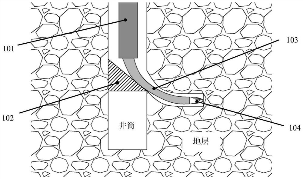
[0008] as Figure 1 As shown, after the completion of the drilling of the oil and gas well, the continuous tubing 101 will be the inclinator 102 and the high-energy pulse spin plasma drill bit 103 into the wellbore, after reaching a specific formation, the inclinator 102 generates an action under the action of the ground control signal, anchoring the casing; the high-energy pulse spin plasma drill bit 103 is biased to the side of the casing under the guiding action of the incliner 102; the ground control system sends out a control signal, and the high-energy pulse spin plasma drill bit 103 sprays out a high-energy pulse spin plasma 104 High-energy pulsed spin plasma melts the casing, annular cement and stratigraphic rock in turn, and continuously drills.

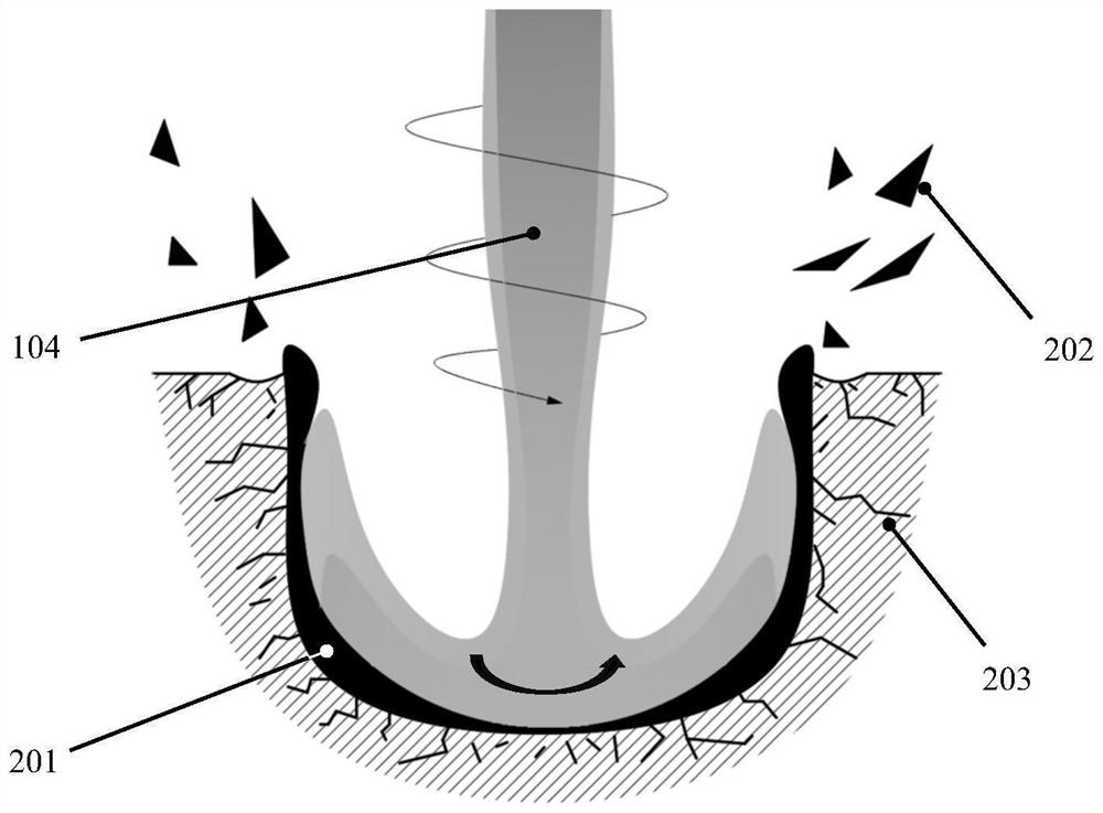
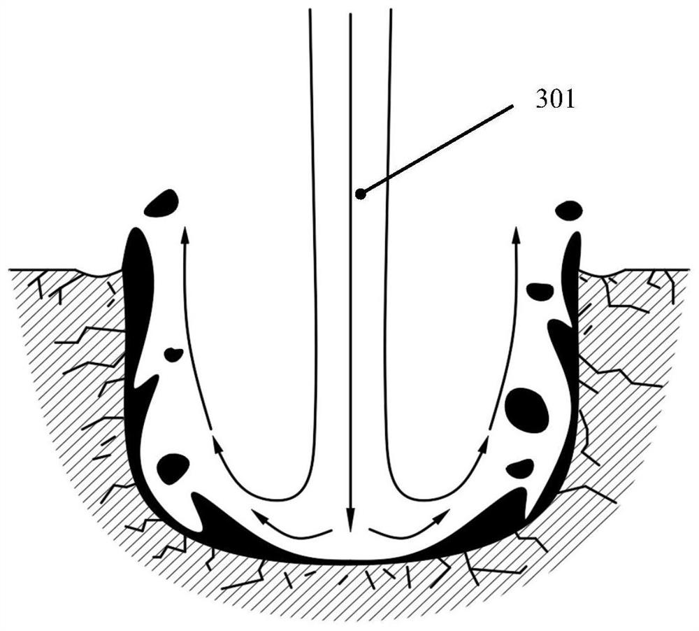
[0009] High-energy pulsed spin plasma 104 is ejected onto the rock surface as schematic Figure 2 As shown, the high-speed rotating high-energy pulse spin plasma 104 melts the rock, and a layer of molten magma is formed on the sur...


PUM


Abstract

The invention belongs to the field of petroleum engineering, and in particular relates to a high-energy pulsed spin plasma perforation method. After the drilling of the oil and gas well is completed, the high-energy pulsed spin plasma drill bit and the whipstock are lowered through the coiled tubing. After reaching a specific formation, the whipstock anchors the casing, and the plasma drill bit deflects under the guidance of the whipstock. One side of the casing; the ground control system sends a control signal, and the plasma drill ejects pulsed spin plasma; the spin plasma melts the casing, annular cement and formation rock in turn; the plasma jet gap, high-pressure spin The air flow is ejected from the plasma nozzle, and the high-pressure spin air flow blows away the molten material in the plasma action area; the spin plasma is repeatedly sprayed, and a high-permeability hole is gradually drilled on the side wall of the wellbore. The method can quickly drill a large-diameter, long-depth high-permeability hole on the side wall of the wellbore, greatly improving the connectivity between the wellbore and the reservoir, and improving the production efficiency and total output of the oil and gas well.

Description

Technical field [0001] The present invention belongs to the field of petroleum engineering, specifically, relates to a high-energy pulsed spin plasma perforation method. Background [0002] In the process of oil and gas exploitation, after the completion of oil and gas well drilling, it is also necessary to use the concentrated energy perforation projectile for perforation operations, open the channel between the wellbore and the reservoir, so that oil and gas resources can enter the wellbore through the channel, and then be exploited to the surface. However, the existing perforation projectile perforation operation has the following deficiencies: the depth of injection into the formation is limited, usually only 0.5 to 1.5m, the diameter is 10 to 15mm, can not effectively penetrate the near well pollution zone; in the process of perforation, there is a compaction effect, resulting in a decrease in the permeability of the rock; the decline in rock permeability directly leads to t...

Claims


Application Information

Patent Timeline
Patent Type & Authority Patents(China)
IPC IPC(8): E21B43/114E21B43/119
CPCE21B43/114E21B43/119
Inventor 刘永红孙强韩延聪刘鹏沈志萍武鑫磊赵莅龙李德格
Owner CHINA UNIV OF PETROLEUM (EAST CHINA)
Learn More