Sensorless brushless motor and control circuit and method thereof

A technology for controlling circuits and motors, used in motor control, electronic commutation motor control, control systems, etc.

Inactive Publication Date: 2009-08-05
INT BUSINESS MASCH CORP
View PDF2 Cites 2 Cited by
  • Summary
  • Abstract
  • Description
  • Claims
  • Application Information

AI Technical Summary

Problems solved by technology

Not surprisingly then, there is considerable problem with calculating the exact commutation instant by the controller 20 when receiving relatively low amplitude back EMF signals

Method used


Image

  • Sensorless brushless motor and control circuit and method thereof
  • Sensorless brushless motor and control circuit and method thereof
  • Sensorless brushless motor and control circuit and method thereof

Examples


Embodiment Construction

[0036] According to a preferred embodiment of the present invention, an improved closed-loop control method of a sensorless brushless DC motor is disclosed. Briefly, automatic gain control (AGC) is used in calculating the neutral voltage to normalize the magnitude of the sensed back EMF, thereby providing improved signal integrity for the zero voltage crossing detection circuit. As a result, reliable closed-loop control can start at an earlier time when the motor is operating at lower speeds.

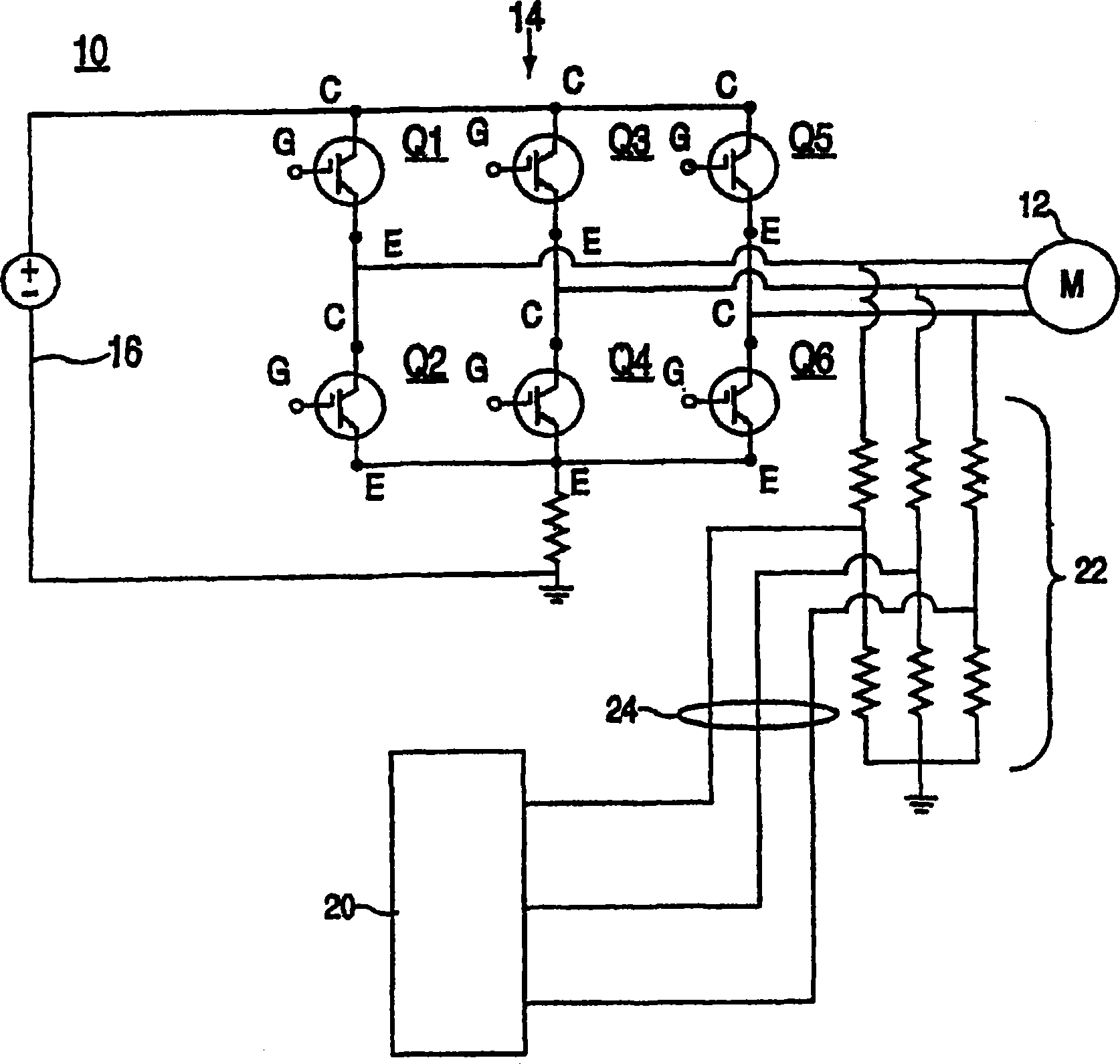
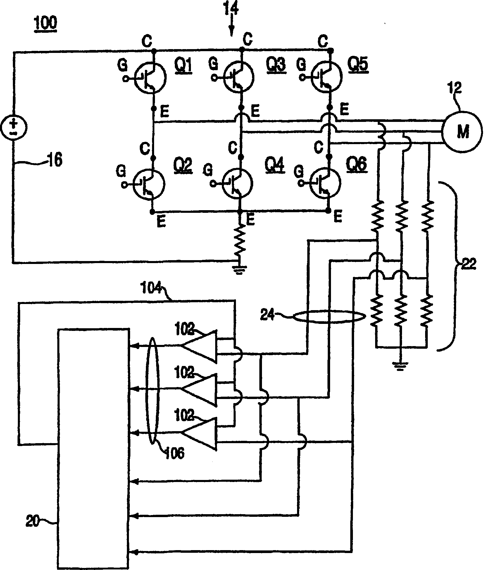
[0037] see now image 3 , which is shown for figure 1 An improved control circuit 100 for sensorless brushless DC motors. For ease of description, with figure 1 The same elements in image 3 are marked with the same reference numerals. Each of the attenuated back EMF phase voltage signals 24 from the motor 12 is coupled to a corresponding automatic gain control (AGC) circuit 102 as shown. Those skilled in the art will recognize that a gain control circuit is a circuit that applies...


PUM


Abstract

A method for electronically commutating a motor having a plurality of phase windings associated therewith is disclosed. In an exemplary embodiment, the method includes sensing a back electromotive force (BEMF) generated by each of the phase windings, and scaling the magnitude of the sensed BEMF values for each of the phase windings to a normalized value to produce gain corrected BEMF signals. The gain corrected BEMF signals are then used to determine a rotor position of the motor.

Description

technical field [0001] The invention relates to a control circuit for a sensorless brushless motor. Background technique [0002] Brushless direct current (DC) motors (electronically commutated motors) are well known in the art. The windings of each phase are sequentially energized at appropriate times to generate a rotating magnetic field associated with the permanent magnet rotor. The timing of the sequential energization is a function of the position of the permanent magnet rotor relative to the particular phase winding being energized. To date, various approaches have been used to sense the position of the permanent magnet rotor relative to each phase winding. These methods include the use of optical sensors and Hall effect devices to feed a position signal to the switching logic circuit, causing the latter to selectively turn on or off the excitation of the corresponding phase windings. However, such sensing devices add cost and complexity to the system and sometimes...

Claims


Application Information

Patent Timeline
Patent Type & Authority Patents(China)
IPC IPC(8): H02P6/18
CPCH02P6/182Y10S388/9281
Inventor T·特里菲洛
Owner INT BUSINESS MASCH CORP
Why Eureka
Try Eureka