High-reliability electric bolt releasing structure and method based on position detection

A reliable and electric technology, used in weapon accessories, offensive equipment, training matching components, etc., can solve problems such as overshoot, high-speed impact, stall, frequent failure, damage to structural parts, etc., to achieve simple closed-loop control and avoid overshoot. Punch, easy to use effect

Pending Publication Date: 2020-04-10
XIAN KEYWAY TECH
View PDF0 Cites 0 Cited by
  • Summary
  • Abstract
  • Description
  • Claims
  • Application Information

AI Technical Summary

Problems solved by technology

The more prominent problems are as follows: 1. It is impossible to know the current real-time position of the bolt-opening slider; 2. When the motor drives the bolt-opening slider to the position of the limit sensors at both ends at high speed through the ball screw, it is easy to produce overshoot, High-speed impact, stalling and other phenomena, frequent failures, damage to structural parts, and unreliability problems such as motor burnout; 3. In order to avoid problems such as overshoot and high-speed impact, low-speed operation is generally adopted but the bolt opening time is prolonged; Run at high speed, and then slow down when the limit is reached. When the initial position of the bolt opening slider is not fixed, this method will easily cause problems; 4. It takes a long time to judge the fault alarm: if a fault occurs during the bolt opening process , the fault state cannot be obtained in time, generally through human judgment, that is, the bolt has not been successfully opened after exceeding the time required for normal bolt opening, and the fault state is obtained through manual or automatic alarm over time, these processing methods are not timely

Method used


Image

  • High-reliability electric bolt releasing structure and method based on position detection
  • High-reliability electric bolt releasing structure and method based on position detection
  • High-reliability electric bolt releasing structure and method based on position detection

Examples


Embodiment Construction

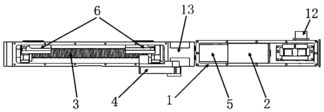
[0017] A high-reliability electric bolt-opening structure based on position detection of the present invention includes a bolt-opening structure housing 1 and a motor 2 arranged in the bolt-opening structure housing 1. The motor 2 is connected to a ball screw 3 through a reducer 5, and the ball screw A bolt-opening slider 4 is threaded on the bar 3, limit sensors 6 are arranged at both ends of the ball screw 3, and a position detection device 13 for real-time detection of the moving position of the bolt-opening slider 4 is connected to the reducer 5. The position detection device 13 is fixedly arranged in the shell 1 of the opening structure.

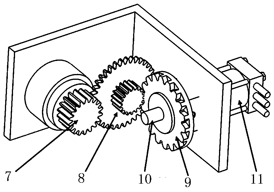
[0018] The position detection device 13 includes a multi-turn potentiometer 11, and a potentiometer shaft 10 is connected to the potentiometer 11 in rotation, and the potentiometer shaft 10 is connected to the speed reducer 5 through a connection device. When the speed reducer 5 passes through the connection device The potentiometer sha...


PUM


Abstract

The invention discloses a high-reliability electric bolt releasing structure and method based on position detection, and relates to the technical field of conventional weapons. The high-reliability electric bolt releasing structure comprises a bolt releasing structure shell and a motor arranged in the bolt releasing structure shell; the motor is connected with a ball screw through a speed reducer,a bolt releasing sliding block is in threaded connection with the ball screw, and limiting sensors are arranged at the two ends of the ball screw; and the speed reducer is connected with a position detection device for detecting the moving position of the bolt releasing sliding block in real time, and the position detection device is fixedly arranged in the bolt releasing structure shell. The bolt releasing structure is simple and convenient to use; the real-time position of the bolt releasing sliding block is detected by the position detection device for detecting the moving position of thebolt releasing sliding block in real time, therefore, the motor can be controlled more accurately, and the problems of overshoot, high-speed impact and the like in the bolt releasing process are avoided under the condition that the bolt releasing time is guaranteed.

Description

technical field [0001] The invention relates to the technical field of conventional weapons, in particular to a high-reliability electric bolt opening structure and method based on position detection. Background technique [0002] With the development of automatic technology products for gun installation, there are many forms of electric bolt opening methods for guns, and the realization methods are basically the same, that is, through the motor, reducer, ball screw, Realized by bit sensor. This method can realize the electric bolt opening of gun, but there are many unreliability. The more prominent problems are as follows: 1. It is impossible to know the current real-time position of the bolt-opening slider; 2. When the motor drives the bolt-opening slider to the position of the limit sensors at both ends at high speed through the ball screw, it is easy to produce overshoot, High-speed impact, stalling and other phenomena, frequent failures, damage to structural parts, an...

Claims


Application Information

Patent Timeline
IPC IPC(8): F41A33/00
CPCF41A33/00
Inventor 刘升苏本斌
Owner XIAN KEYWAY TECH
Why Eureka
Try Eureka