Supercharge Your Innovation With Domain-Expert AI Agents!

Fast exchanging mechanism for clamping head

A collet and rotating sleeve technology, applied in the direction of clamping, metal processing mechanical parts, supports, etc., can solve the problems of unreliable prevention of disengagement, easy wear and failure, etc., to achieve reliable connection, convenient installation and disassembly, operation method simple effect

Inactive Publication Date: 2009-08-12
POSITEC POWER TOOLS (SUZHOU) CO LTD
View PDF11 Cites 0 Cited by
  • Summary
  • Abstract
  • Description
  • Claims
  • Application Information

AI Technical Summary

Problems solved by technology

For example, U.S. Patent No. US6551037 discloses a collet quick-change mechanism. By inserting the protrusion on the collet swivel into the opening on the main shaft, and turning a rotating ring at the same time, the protrusion on the swivel cannot run from the main shaft opening. out, so that the collet is installed on the main shaft, since the locking mechanism is realized by the abutment of the cam surface, it is easy to wear and fail
U.S. Patent No. US5211693 discloses a collet quick-change mechanism, which realizes collet locking by radially moving the dislocation of the teeth, but the clamping force of the locking collet is generated by radially moving elastic elements , cannot reliably prevent disengagement

Method used


Image

  • Fast exchanging mechanism for clamping head
  • Fast exchanging mechanism for clamping head
  • Fast exchanging mechanism for clamping head

Examples


Embodiment Construction

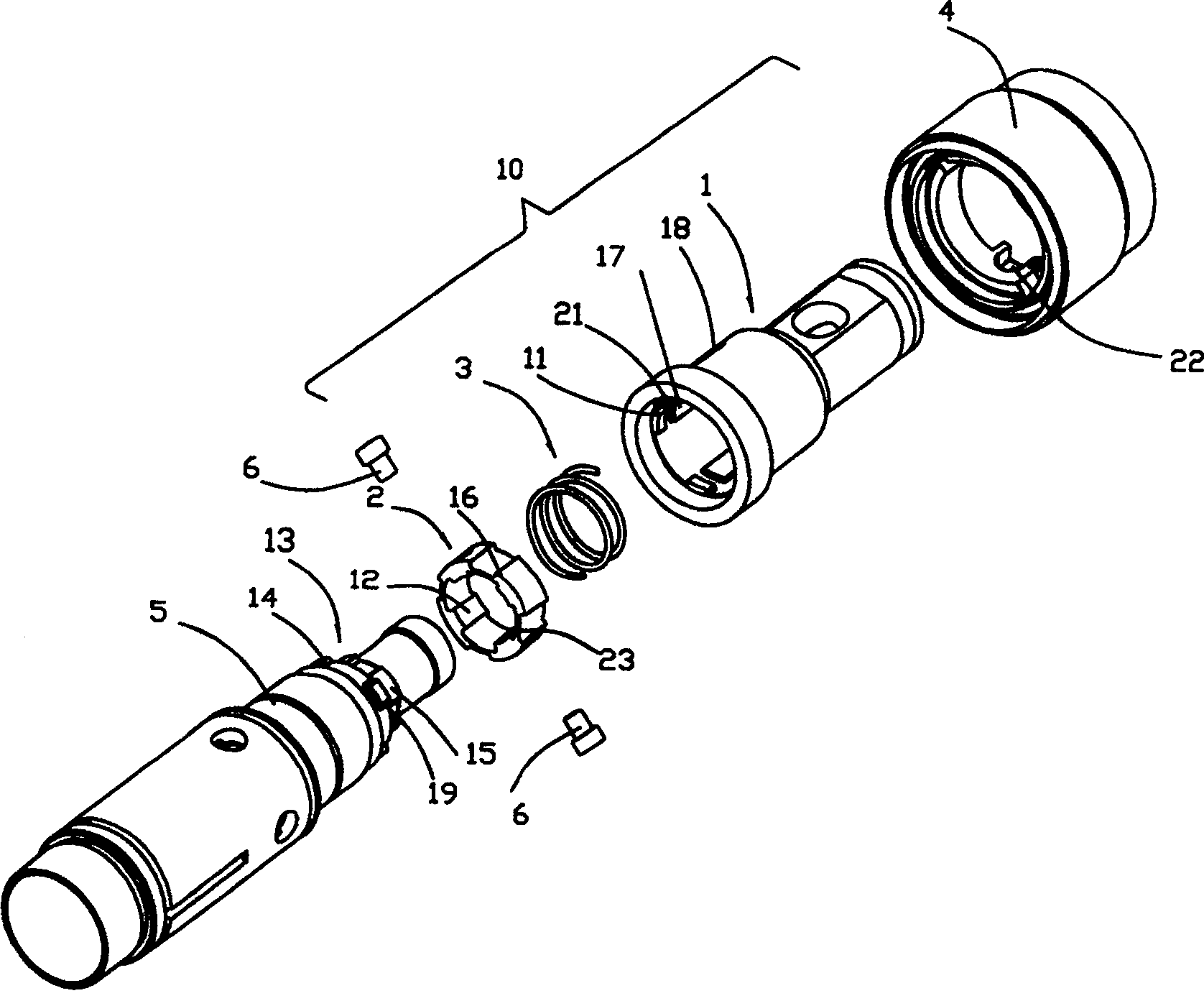
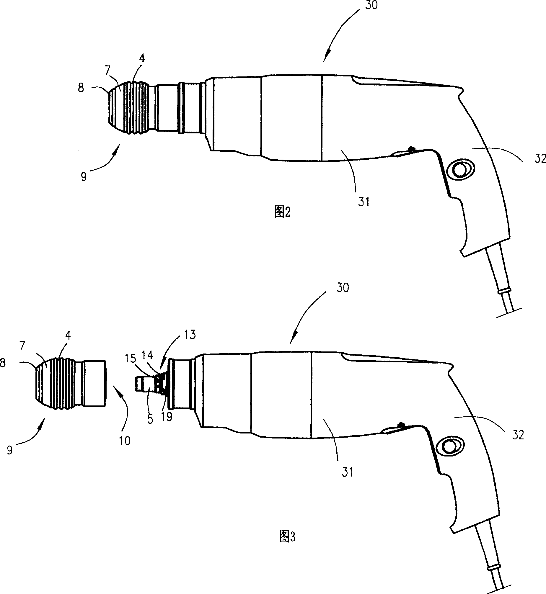
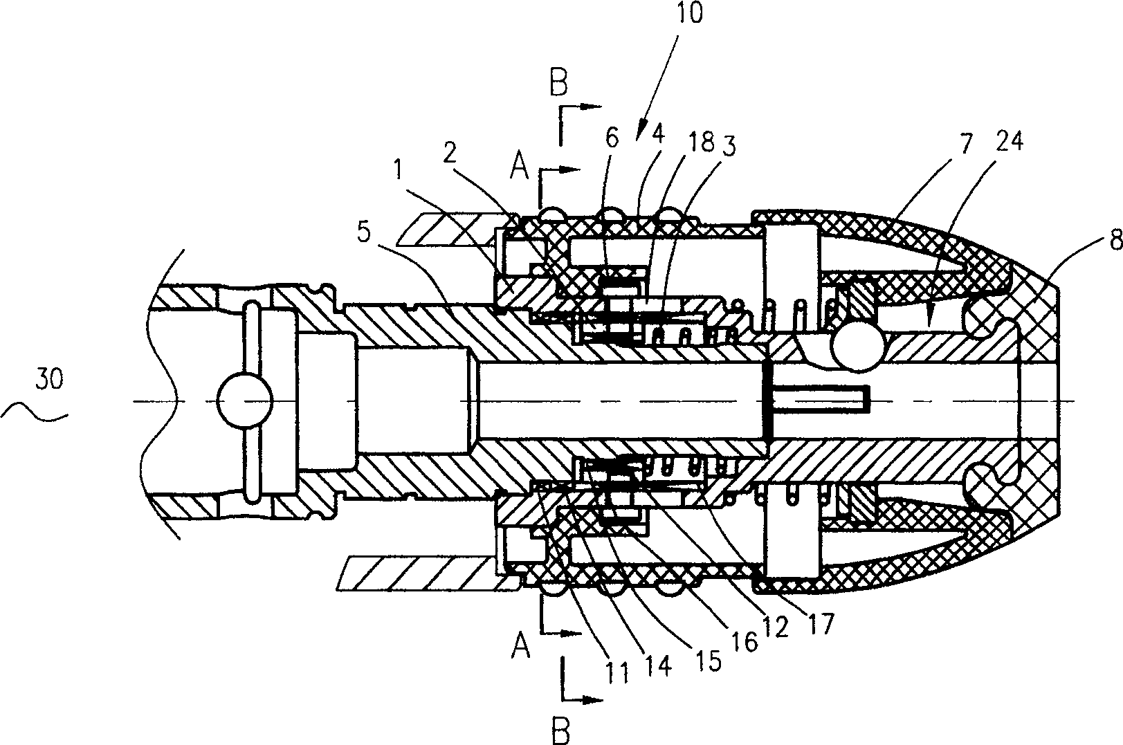
[0021] See attached Figure 1~3 , the present invention discloses a chuck quick change mechanism 10 . The collet quick change mechanism 10 detachably installs the collet 9 on the main shaft 5 of the electric tool 30 . The electric tool 30 includes a tool body 31 , a handle 32 located at the rear of the tool body 31 , a drive unit and a transmission unit (not shown) accommodated inside the tool body 31 , and a spindle 5 connected to the transmission unit. In the present invention, the electric tool 30 is an electric hammer.

[0022] The main shaft 5 includes an inner surface and an outer surface. Wherein the outer surface is provided with a positioning piece 13 and a first groove 19 . In this preferred embodiment, the positioning member 13 includes a first external spline 14 and a second external spline 15 , and the outer diameter of the first external spline 14 is larger than the outer diameter of the second external spline 15 . The first groove 19 is located on the side o...


PUM


Abstract

The invention discloses a collet quick-change mechanism (10). The collet (9) is detachably installed on a main shaft (5) provided with a positioning part (13), including a first limiting part (11) ), the connecting sleeve (2) between the rotating sleeve (1) and the main shaft (5), the elastic member (3) between the rotating sleeve (1) and the connecting sleeve (2) And the driving member (4) sleeved on the outside of the rotating sleeve (1), the first limiting member (11) cooperates with the positioning member (13) to limit the axial displacement of the rotating sleeve (1) relative to the main shaft (5), and the connecting sleeve (2) A second limiter (12) is provided to cooperate with the positioning member (13) to limit the rotation of the connecting sleeve (2) relative to the main shaft (5), and the driving member (4) drives the connecting sleeve (2) relative to the rotating sleeve ( 1) Axial movement. The chuck quick change mechanism (10) is reliable in structure and easy to operate.

Description

technical field [0001] The invention relates to an electric tool, in particular to a chuck quick-change mechanism on the electric tool. Background technique [0002] At present, users apply electric drills and electric hammers to various operating occasions respectively. In order to enable the same tool to easily replace the twist drill and the hammer drill by simply replacing the working head, while ensuring that the twist drill still maintains sufficient accuracy, people use a collet quick-change mechanism to achieve the above purpose. For example, U.S. Patent No. US6551037 discloses a collet quick-change mechanism. By inserting the protrusion on the collet swivel into the opening on the main shaft, and turning a rotating ring at the same time, the protrusion on the swivel cannot run from the main shaft opening. out, so that the collet is installed on the main shaft, since the locking mechanism is realized by the abutment of the cam surface, it is easy to wear and fail. ...

Claims


Application Information

Patent Timeline
Patent Type & Authority Patents(China)
IPC IPC(8): B23B31/113B23Q3/12B25D17/08
Inventor 丁水澄
Owner POSITEC POWER TOOLS (SUZHOU) CO LTD
Features
  • R&D
  • Intellectual Property
  • Life Sciences
  • Materials
  • Tech Scout
  • Unparalleled Data Quality
  • Higher Quality Content
  • 60% Fewer Hallucinations
Learn More