Rotating anchor rod of a rod and construction method thereof
A rod body and anchor rod technology, which is applied in the installation of anchor rods, sheet pile walls, excavation, etc., to achieve the effects of saving materials, combining tightly, and avoiding underground hazards
- Summary
- Abstract
- Description
- Claims
- Application Information
AI Technical Summary
Problems solved by technology
Method used
Image

Examples
Embodiment 1
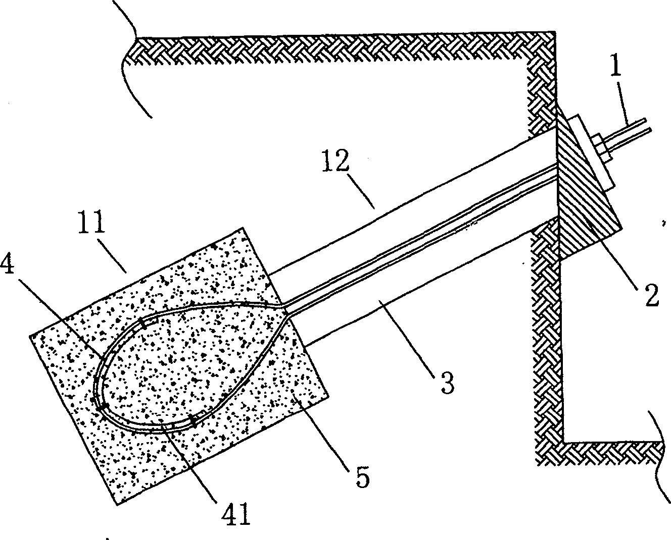
[0040] like figure 1As shown, the present invention consists of the flexible anchor rod body 1 placed in the anchor hole after rotation, the grout body 5 and the anchor head fixing part 2 bonded to the anchor rod body after the grout poured into the anchor hole 3 is solidified The anchor rod body 1 is composed of rotatable and bendable steel strands, steel wire ropes, steel wire bundles or engineering plastics, and is placed in the anchor hole 3. The anchor hole 3 is divided into an anchoring section 11 and a free section 12, wherein the anchor rod body 1 The straight section is placed in the free section 12, the rotary section is placed in the anchor hole anchor section 11, and the end is placed outside the anchor hole 3, which is convenient for control during recovery. It is characterized in that: on the rotary section of the anchor rod body 1, A supporting piece 4 is provided, and the supporting piece 4 can be deformed according to the rotation shape of the anchor rod body ...
Embodiment 2
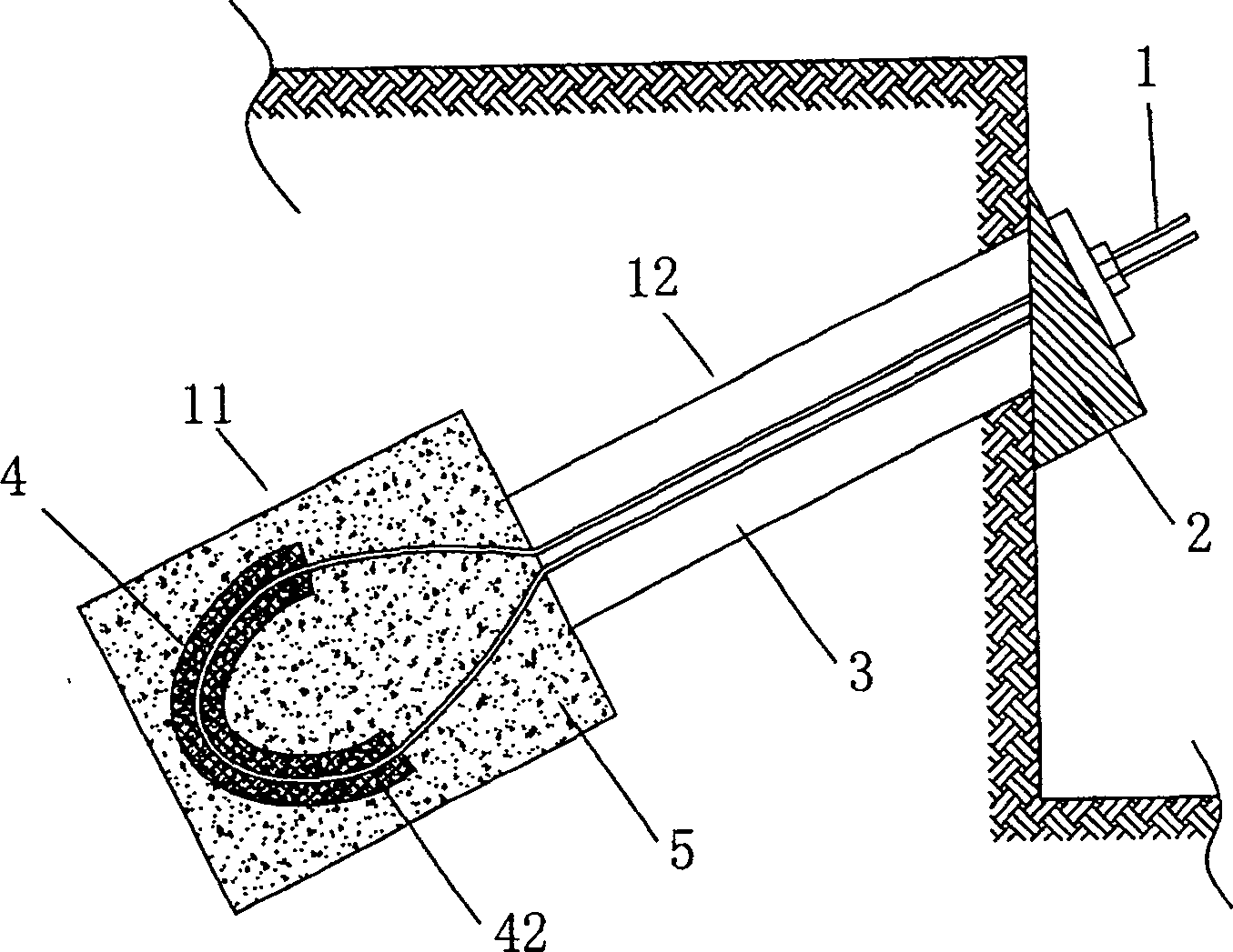
[0048] like figure 2 As shown, the anchor rod body 1, the grouting body 5 and the anchor rod head fixing part 2 in this embodiment are the same as those in the first embodiment, the difference is that the bracket 4 can cover the surface of the turning section of the anchor rod body 1 The mesh member 42, as shown in the figure, the mesh member 42 can be an elastic, bendable mesh, the mesh can be made of metal wires, or can be made of other materials, and can also be a three-dimensional with a certain thickness. It is a flexible and elastic mesh member. When the mesh is thin, it can be wrapped in multiple layers, or it can be made by repeatedly winding the mesh. It is attached to the anchor rod body by wire tie or other fastening methods. 1 rotation The outer surface of the section is deformed according to the rotation shape of the bolt body 1, and the mesh aperture on it can fully allow the grout to pass through and infiltrate. When the rotary anchor rod is placed in the anch...
Embodiment 3
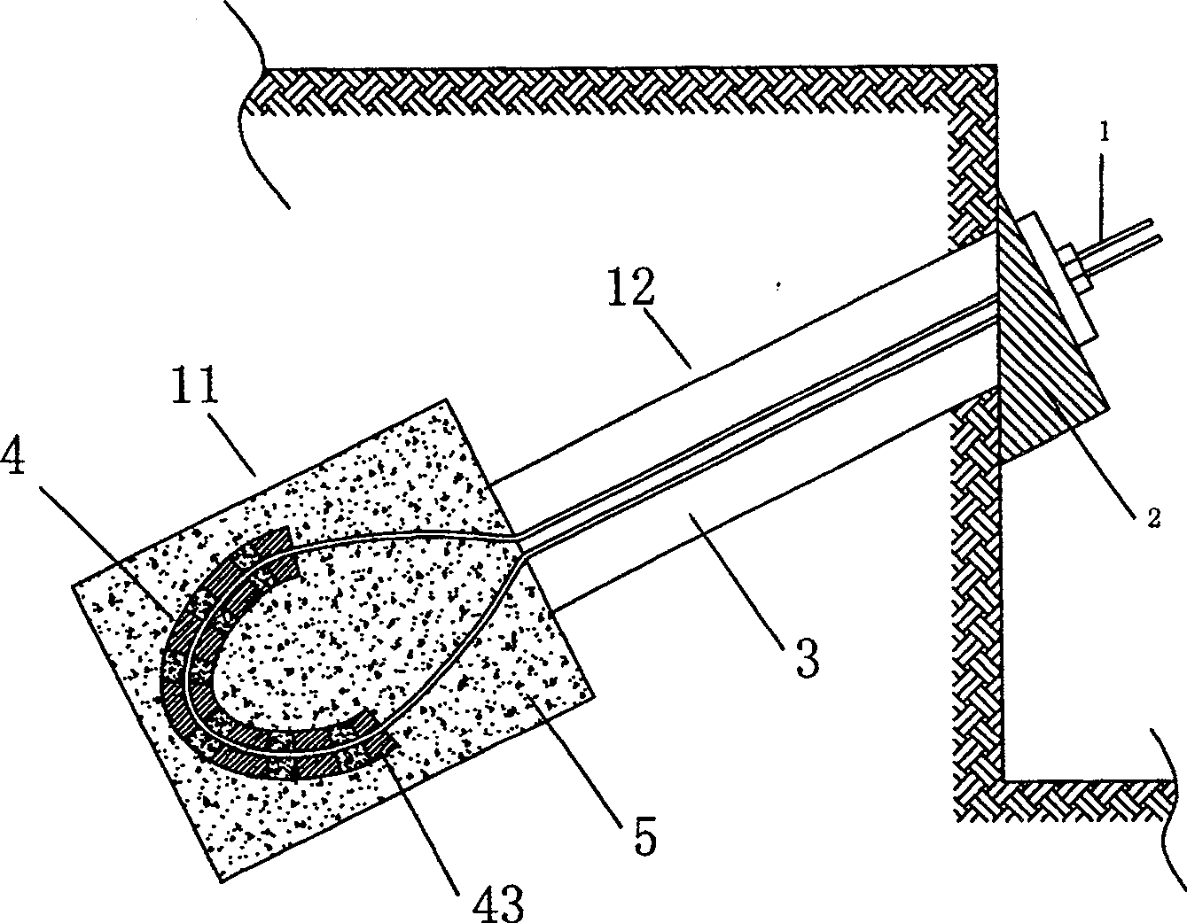
[0056] like image 3 As shown, the anchor rod body 1, the grouting body 5 and the anchor rod head fixing member 2 in this embodiment are the same as those in the first and second embodiments, the difference is that the supporting member 4 is a sleeve set on the surface of the rotating section of the rod body Sleeve 43, as shown in the figure, the sleeve 43 can be a perforated elastic sleeve or the side wall of the sleeve has a mesh structure, and it is attached outside the turning section of the anchor rod body 1 through iron wire tie or other fastening methods The surface is deformed according to the rotation shape of the bolt body 1, and the upper hole diameter can fully allow the grout to pass through and infiltrate. When the rotary anchor rod is placed in the anchor hole 3, the sleeve 43 can be combined with the grout during grouting, so that the consolidated body after grouting forms a carrier with a sleeve skeleton, which improves the grouting body 5. strength, and can ...
PUM
 Abstract
Description
Claims
Application Information
 - R&D
- Intellectual Property
- Life Sciences
- Materials
- Tech Scout
- Unparalleled Data Quality
- Higher Quality Content
- 60% Fewer Hallucinations
Browse by: Latest US Patents, China's latest patents, Technical Efficacy Thesaurus, Application Domain, Technology Topic, Popular Technical Reports.
© 2025 PatSnap. All rights reserved.Legal|Privacy policy|Modern Slavery Act Transparency Statement|Sitemap|About US| Contact US: help@patsnap.com