Heatable floor structure and method of constructing the same
A construction method and flooring technology, applied to heating methods, building structures, hot water central heating systems, etc., to achieve the effects of simple construction work, prevention of peeling, and simple operation
- Summary
- Abstract
- Description
- Claims
- Application Information
AI Technical Summary
Problems solved by technology
Method used
Image
Examples
Embodiment 1
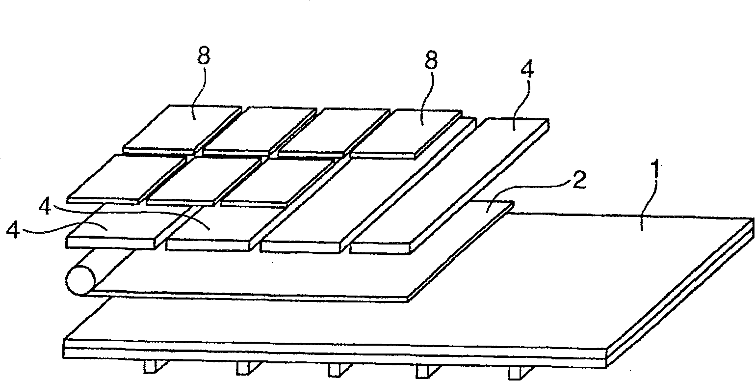
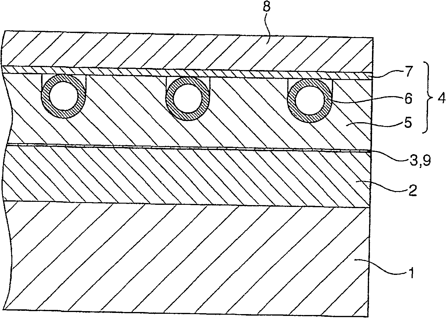
[0098] figure 1 and figure 2 Among them, symbol 1 is an existing floor with an area of 360 cm×270 cm, and the high specific gravity sheet 2 rolled into a roll is arranged on the surface of the existing floor 1 . High specific gravity sheet 2 uses thickness 1mm, width 350cm, length 360cm, density 2.5g / cm 3 rubber sheet containing filler (manufactured by Hayakawa Rubber Co., Ltd.). There is no adhesive agent at the interface between the existing floor 1 and the high specific gravity sheet (rubber sheet containing filling material) 2, and no small screws or nails are screwed. Utilize acrylic adhesive (manufactured by Sanyo Chemical Industry Co., Ltd., trade name "Polysix") on the surface of the high specific gravity sheet 2 to stick it with a thickness of 1 mm and an amount per unit of 120 g / m 2 nonwoven fabric 3 (manufactured by Toa Textile Co., Ltd.).
[0099] Next, the heating panel 4 is arranged on the upper side of the high specific gravity sheet 2 . The heating plat...
Embodiment 2
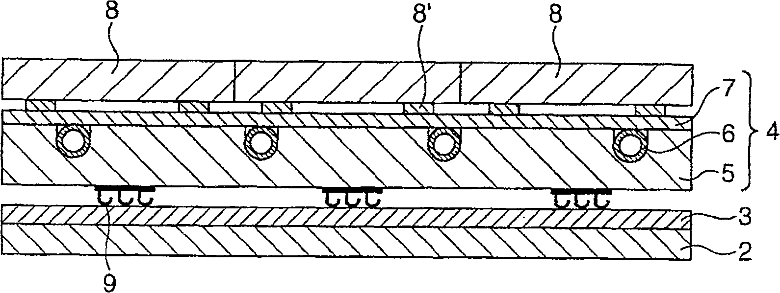
[0103] right Figure 5 The floor structure shown was constructed. Figure 5 Floor structure shown with image 3 Compared with the shown structure, there are mainly the following differences, that is, by pasting the surface fastener 9 on the surface of the high specific gravity sheet 2, and pasting the non-woven fabric 3 on the back side of the heating plate 4, the heating plate 4 is fixed on the high specific gravity sheet 2 superior. in progress Figure 5In the construction of the floor structure shown, when laying the heating surface 4, the partition sheet 10 is arranged on the non-woven fabric 3 on the surface of the high specific gravity sheet 2, and the heating plate 4 is temporarily arranged on it, and the position is aligned, and then, The heating panel 4 is rolled up, and the partition sheet 10 is removed. At the same time, the heating panel 4 is pressed from the upper side, thereby, the non-woven fabric 3 pasted on the surface side of the high specific gravity shee...
Embodiment 3
[0105] right Figure 6 The floor structure shown was constructed. Figure 6 Floor structure shown with Figure 1~5 Compared with the shown structure, there are mainly the following differences, that is, the high specific gravity sheet 2 is arranged on the heating plate 4, and the surface decoration material 8 is arranged on the high specific gravity sheet 2 through the partition material 11. As the high specific gravity sheet 2, same as Example 1, it is a sheet rolled into a roll shape, and its thickness is 2 mm, width 909 cm, length 500 cm, density 2.0 g / cm 3 rubber sheet containing filler (manufactured by Hayakawa Rubber Co., Ltd.). In addition, the high specific gravity sheet 2 has a release paper attached to it, and only a part of it is peeled off for use. In addition, the heating board 4 used the same heating board as Example 1 and 2. As shown in FIG.
[0106] in progress Figure 6 In the construction of the floor structure shown, a heating panel 4 is arranged on the...
PUM
 Abstract
Description
Claims
Application Information
 - R&D
- Intellectual Property
- Life Sciences
- Materials
- Tech Scout
- Unparalleled Data Quality
- Higher Quality Content
- 60% Fewer Hallucinations
Browse by: Latest US Patents, China's latest patents, Technical Efficacy Thesaurus, Application Domain, Technology Topic, Popular Technical Reports.
© 2025 PatSnap. All rights reserved.Legal|Privacy policy|Modern Slavery Act Transparency Statement|Sitemap|About US| Contact US: help@patsnap.com


