
An electrical connector

A technology of electrical connectors and electrical connection devices, which is applied in the direction of connections, circuits, and parts of connection devices, etc., which can solve the problems that screws and spring washers do not have electrical characteristics, and achieve the effect of easy assembly and low cross-sectional area

Active Publication Date: 2009-08-26
领先电子国际公司
View PDF5 Cites 0 Cited by
  • Summary
  • Abstract
  • Description
  • Claims
  • Application Information

AI Technical Summary

Problems solved by technology

Also, the screws and spring washers themselves do not have sufficient electrical characteristics

Method used


Image

  • An electrical connector
  • An electrical connector
  • An electrical connector

Examples


Embodiment Construction

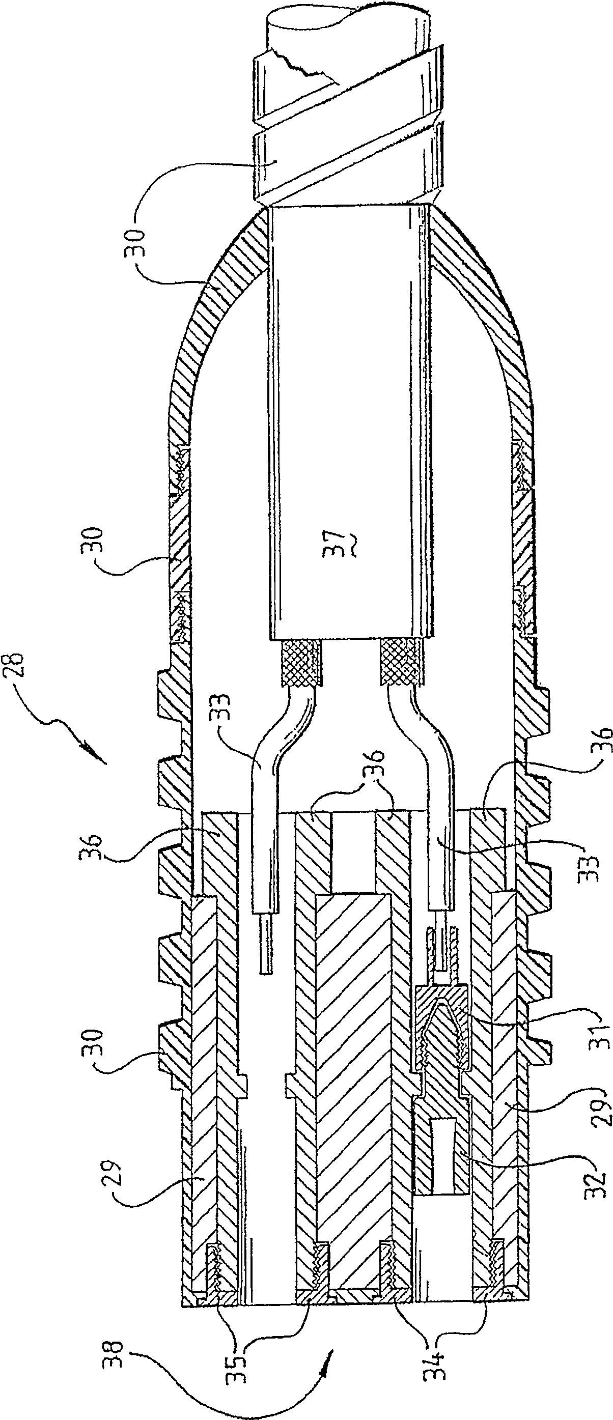
[0033] see image 3 , detailing a socket including an electrical connector according to a specific embodiment. The plug connector 28 includes a socket 32 ​​and a connector 31 . In this embodiment, the socket 32 ​​and the joint 31 are each integrally formed. The connector 31 is connected to the core 33 of the machine cable 37 . The receptacle 32 is adapted to accept a plug (not shown) and has a threaded post portion which interlocks with the threaded hole of the fitting 31 .

[0034] The plug connector 28 includes an approximately cylindrical body 29 and a housing 30 made of metal and / or insulating material. The socket 28 has an end face 38 in which there are three holes defined by nuts such as nuts 34 and 35 . An insulating sleeve 36 protrudes toward the inside of each hole. The joint 31 has a key (not shown), and the sleeve 36 has a corresponding keyway (not shown), thereby restricting the rotation of the joint 31 in the sleeve 36 and simplifying the connection of the soc...


PUM


Abstract

The invention provides an electrical connector for connecting the core of a machine cable (37) to a plug (28) or socket (32) of an electrical connection device. The connector has a first part and a second part. The first and second components respectively have first and second locking surfaces and first and second separate contact surfaces (50, 52). The second part also includes a protrusion for securing the core of the machine cable, and the protrusion is electrically connected to the second contact surface. The contact surfaces are arranged such that when the locking surfaces are interlocked, the contact surfaces are in electrical contact with each other, thereby establishing electrical contact between the machine cable and the plug or socket.

Description

technical field [0001] The present invention generally relates to an electrical connector for connecting the core of a machine cable to a plug or socket of an electrical connection device. Throughout the specification the term "machine cable" may be any machine, machine, reeling or trailing cable used to deliver electrical power to moving motors such as large motors used in the petroleum or mining industries. The term "connector" may be any connector including a plug, lug, electrical adapter, fitting or receptacle. Background technique [0002] Machine cables are often used to provide electrical connections to moving generators. For example, in the mining or petroleum industries, where large generators are often used, each machine cable must supply power on the order of several hundred kilowatts. Typically, this power is delivered at a thousand volts or more. Cables usually contain multiple cores joined together by connectors with sockets and plugs. [0003] Figure 1 sho...

Claims


Application Information

Patent Timeline
Patent Type & Authority Patents(China)
IPC IPC(8): H01R13/639
Inventor 马克·韦尔斯
Owner 领先电子国际公司
Learn More