Extruder

A technology for extruders and processing units, applied in the field of extruders, can solve problems such as interference, and achieve the effects of simplified loading and light cost

Active Publication Date: 2009-09-23
BLACH VERWALTUNGS GMBH
View PDF2 Cites 0 Cited by
  • Summary
  • Abstract
  • Description
  • Claims
  • Application Information

AI Technical Summary

Problems solved by technology

[0003] However, as has been proven, plastics extruded through extruders with such barriers have a large number of black spots, so-called "black spots", which are especially found in transparent plastics such as PET. are highly intrusive in the resulting product

Method used


Image

  • Extruder
  • Extruder
  • Extruder

Examples


Embodiment Construction

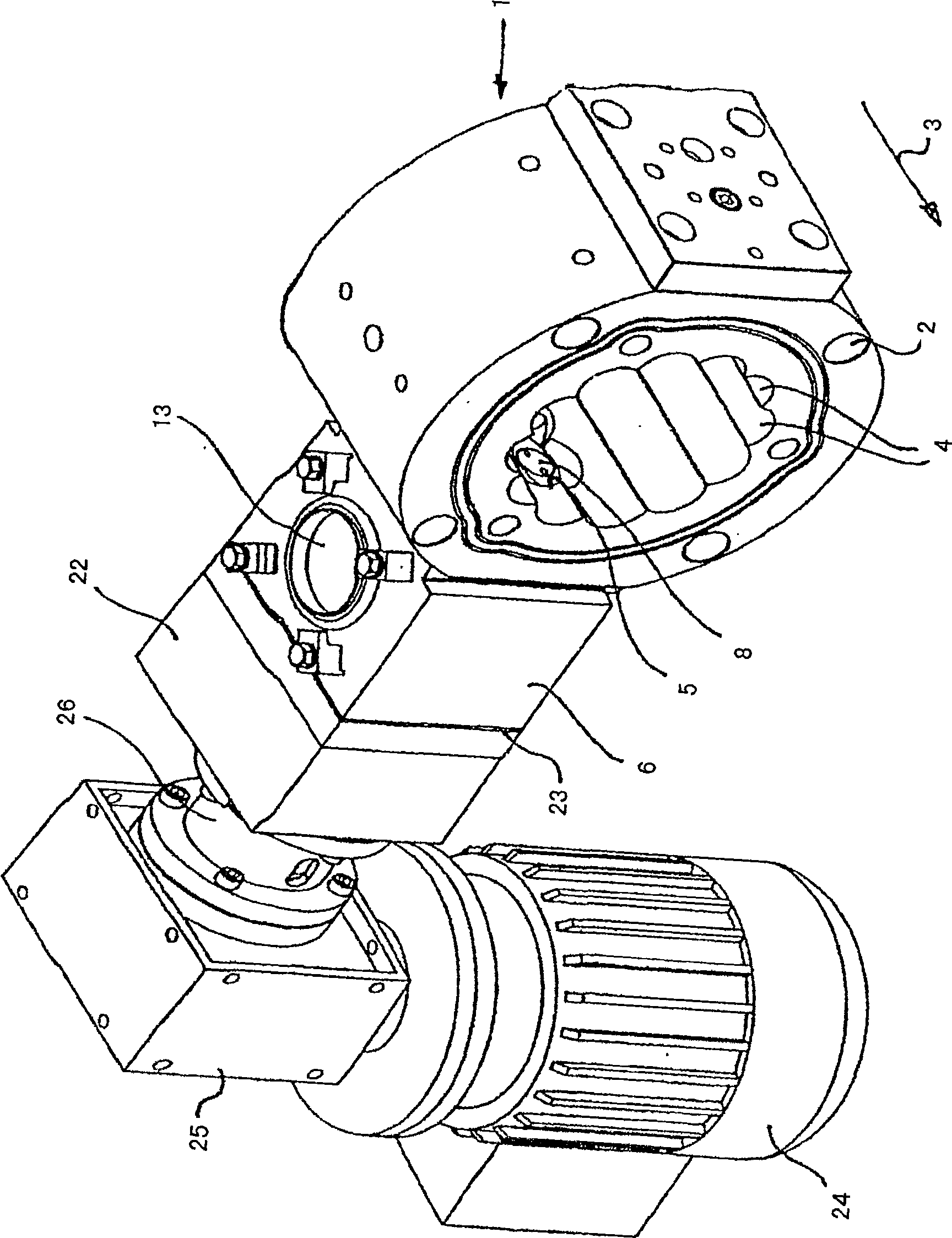
[0024] according to figure 1 Only one housing section 1 of the processing section of the extruder is shown. The treatment part consists of a plurality of such housing sections connected in series, which can be pulled together by tension rods, not shown, which pass through holes 2 in the housing section 1 .

[0025] The transport direction of the treatment section is indicated by arrow 3 . A housing section (not shown) with a material inlet opening is arranged upstream of the delivery of section 1 and a housing section (not shown) with a material outlet opening of the extruder is arranged downstream of the delivery.

[0026] The processing section is configured as an annular extruder, for example as described in EP 0 788 867 B1. That is to say that an inner core, not shown, extends axially through the housing section 1 of the treatment part and the remaining housing sections, not shown. An annular space is formed between the inner core and the housing section, in which space...


PUM


Abstract

The extruder has a processing section with a housing in which at least one screw shaft is arranged, the housing being provided at one end with a material inlet orifice for the material to be processed, On the other end there is a material discharge orifice for the processed material and an intermediate orifice is provided between the material inlet orifice and the material discharge orifice for the discharge of gases from the treatment section (5), a material blocking device is connected to the middle orifice, the material blocking device has at least one screw shaft (7, 8) in an intermediate housing (6), and the screw shaft is connected from the middle orifice ( 5) A gas discharge orifice (13) extending into the intermediate housing (6) and feeding material squeezed into the intermediate housing (6) back into the treatment section. In this case, the screw section (9, 10) of the screw shaft (7, 8) facing the treatment section has a direction of pitch which feeds back into the treatment section and the screw shaft (7, 8) faces away from the treatment section. The screw segments (11, 12) of the processing section have opposite lead angle directions.

Description

technical field [0001] The present invention relates to an extruder. Background technique [0002] Extruders are widely used for conveying and reprocessing raw materials. In order to separate the gas during the processing of the plastic in the extruder in which the solid to viscous plastic is processed, a gas outlet opening is provided in the housing of the processing section of the extruder. In order to prevent the escape of plastic from the treatment part through the opening, a material stop is provided, which is also referred to as a "stopper". The material blocking device has one or two screw shafts, the screw of which has a direction of lift over the entire length, through which the material blocking device presses the plastic entering the orifice back into the processing part , while the gas passing through the screw can be sucked out. [0003] However, as has been proven, plastics extruded through extruders with such barriers have a large number of black spots, so-...

Claims


Application Information

Patent Timeline
Patent Type & Authority Patents(China)
IPC IPC(8): B29C47/76B29C48/03B29C48/39B29C48/40B29C48/41B29C48/69B29C48/76
CPCB29C47/68B29C47/0009B29C47/763B29C47/767B29C47/369B29C48/03B29C48/39B29C48/69B29C48/763B29C48/767B29C48/41B29C48/40
Inventor 约瑟夫·A.·布拉赫
Owner BLACH VERWALTUNGS GMBH
Why Eureka
Try Eureka