Ion mobility TOF/MALDI/MS using drift cell alternating high and low electrical field regions

a high and low electrical field, drift cell technology, applied in the field of ion focusing, can solve the problems of significant ion loss, achieve the effect of improving ion transmission, improving mobility resolution, and simple implementation of collision-induced

Active Publication Date: 2006-01-31
IONWERKS
View PDF8 Cites 51 Cited by
  • Summary
  • Abstract
  • Description
  • Claims
  • Application Information

AI Technical Summary

Benefits of technology

[0020]The present invention makes clear the reason for focusing effect of such type of fields and enhances it, namely, by applying alternating high and low electric fields, and implements other advantages of this approach providing better mobility resolution and relatively simple implementation of collisionally-induced fragmentation of selected ions. The other suggestion mention in this, patent is using of micro-channel plates for inserting of ions from mobility cell with relatively high gas pressure into low pressure region of mass-spectrometer. Such an approach can result in significant ion losses. To improve ion transmission through such micro-channel plates the faces and / or the interior surfaces of the microchannels are coated by thin dielectric film and various means of charging of this film by ions of the same sign as the desired analyte ions are herein now. A mulitpole radio frequency (RF) focusing and beam forming optic is proposed to create and transport ions emerging from a multichannel ion mobility cell wherein multiple ion sources are simultaneously or sequentially injected each into its own individual channel. The action of the RF multipole optic is to maintain the physical separation of the individual mobility separated ions from each multichannel and to create and maintain a substantially parallel array of beamlets (which are themselves substantially parallel trajectories of ions emerging from each mobility channel) between the exit of the mobility cell- and the entrance to the extractor region of a TOFMS. The RF focusing and transport optic may be located before or after a differentially pumped gas skimmer region or may have gas skimmer regions incorporated into its optical design.
[0022]The present invention is directed to a system and method relating to ion mobility drift cells transporting ions in a gas at high pressures. Ions entering such a drift cell travel to the end of the cell under the effect of an electrical field. Differences in molecular shape allow separation of ions according to their ion mobility drift time. This cell can also be applied as a pre-separation stage prior to a time-of-flight mass spectrometer (TOF) for the analysis of complex mixtures of chemical and / or biological substances. This cell allows for cooling the entering ions and transmitting a large fraction of them. Ion losses through decomposition or discharging of electrodes are limited by using special geometry of electrodes and alternating strong and weak field regions within the cell. The application of high field is carefully applied over a distance which is less than the mean free path of the gas within the ion mobility cell. This principle allows the application of several hundred volts / mm before gas discharge occurs. Such high voltages can be used to continually refocus the ions as they periodically pass through the strong field regions. High mobility resolution is nevertheless maintained because the ion trajectories are always randomized after each refocusing so that the distance traveled by each ion over the dimensions of the mobility cell averages to nearly the same distance. Also, the application of higher voltage between selected electrodes in the cell can provide spatially localized collision induced dissociation of ions and their fragments for the efficient structural identification (sequencing) of complex biological analytes. When higher voltages are desirably applied to intentionally create a discharge, the discharge dose not propagate along the length of the cell because it is nicely localized by the low field regions on either side.

Problems solved by technology
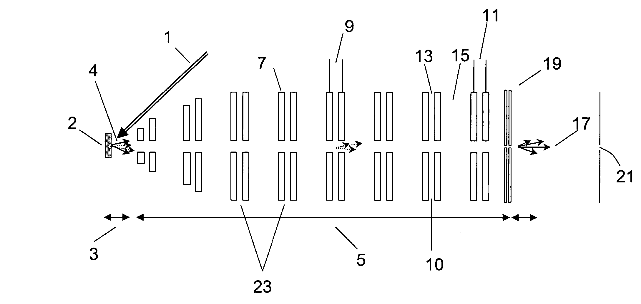
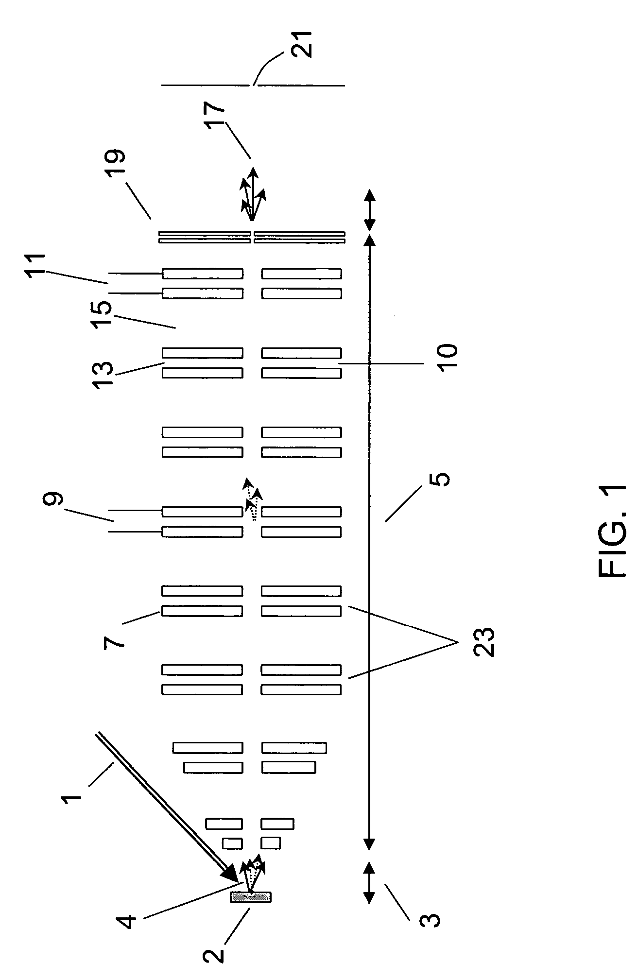
Such an approach can result in significant ion losses.

Method used


Image

  • Ion mobility TOF/MALDI/MS using drift cell alternating high and low electrical field regions
  • Ion mobility TOF/MALDI/MS using drift cell alternating high and low electrical field regions
  • Ion mobility TOF/MALDI/MS using drift cell alternating high and low electrical field regions

Examples


Embodiment Construction

[0056]As used herein, “a” or “an” means one or more. Unless otherwise indicated, the singular contains the plural and the plural contains the singular.

[0057]As used herein, “aperture” means “hole” or “orifice”.

[0058]As used herein, an “electrode triad” is a distinct group or cluster of three electrodes.

[0059]As used herein, the term “intra-electrode gap” refers to the gap between two electrodes of an electrode pair.

[0060]As used herein, the term, “inter-electrode gap” refers to the gap between electrode pairs.

[0061]As used herein, “MALDI” means matrix assisted laser desorption ionization.

[0062]As used herein, “SIMS” means secondary ion mass spectrometry.

[0063]As used herein, the term “TOF” is defined as a time-of-flight mass spectrometer; as used herein, “oTOF” is defined as a time-of-flight mass spectrometer configured orthogonally to the analytical axis of a preceding instrumental platform such as, for example, the separation axis of an ion mobility cell.

[0064]As used herein IM-oT...


PUM

PropertyMeasurementUnit
areaaaaaaaaaaa
diameteraaaaaaaaaa
pressuresaaaaaaaaaa

Abstract

Improved ion focusing for an ion mobility drift cell allows for improved throughput for subsequent detection such as mass detection. Improved focusing is realized by the use of alternating regions of high and low electric fields in the ion mobility drift cell.

Description

CROSS-REFERENCE TO RELATED APPLICATION[0001]This application claims priority to U.S. application Ser. No. 60 / 512,825, filed on Oct. 20, 2003.STATEMENT REGARDING FEDERALLY SPONSORED RESEARCH OR DEVELOPMENT[0002]This work has been funded in whole or in part with Federal funds from the National Institute on Drug Abuse, National Institutes of Health, Department of Health & Human Services under Contract No. N44DA-3-7727. The United States government may have certain rights in the invention.TECHNICAL FIELD[0003]The present invention relates generally to instrumentation and methodology for characterization of chemical samples based on improved ion mobility spectrometry (IMS). Specifically, the improvements lie in the area of ion focusing. The improved focusing may be used to improve throughput from an IMS instrument to a downstream instrument and method, preferably mass spectrometry (MS). The resulting instrument and method are useful for qualitative and / or quantitative chemical and biolog...

Claims


Application Information

Patent Timeline
Patent Type & Authority Patents(United States)
IPC IPC(8): B01D59/44G01NG01N27/64H01J49/00H01J49/40
CPCG01N27/622H01J49/0045G01N27/623
Inventor SCHULTZ, J. ALBERTRAZNIKOV, VALERIEGAN, THOMAS F.UGAROV, MICHAEL V.TEMPEZ, AGNES
Owner IONWERKS
Why Eureka
Try Eureka