Light-emitting device and electronic apparatus

A technology for light-emitting devices and light-emitting elements, which can be applied to lighting devices, electric solid-state devices, electroluminescent light sources, etc., can solve problems such as inability to obtain sealing, cracking of organic EL elements, and deterioration of organic EL elements.

Inactive Publication Date: 2009-09-30
SEIKO EPSON CORP
View PDF9 Cites 0 Cited by
  • Summary
  • Abstract
  • Description
  • Claims
  • Application Information

AI Technical Summary

Problems solved by technology

When the gas barrier layer is cracked or peeled off, the moisture contained in the external atmospheric components will intrude, so there is a problem that the organic EL element cracks significantly
In addition, in order to prevent cracks, an organic compound material with a low elastic modulus is used to form the gas barrier layer, or if the gas barrier layer is made too thin, even if there is no crack or peeling of the gas barrier layer, sufficient sealing performance cannot be obtained, and the organic EL is still damaged. Components bring about early degradation

Method used


Image

  • Light-emitting device and electronic apparatus
  • Light-emitting device and electronic apparatus
  • Light-emitting device and electronic apparatus

Examples


no. 2 Embodiment approach

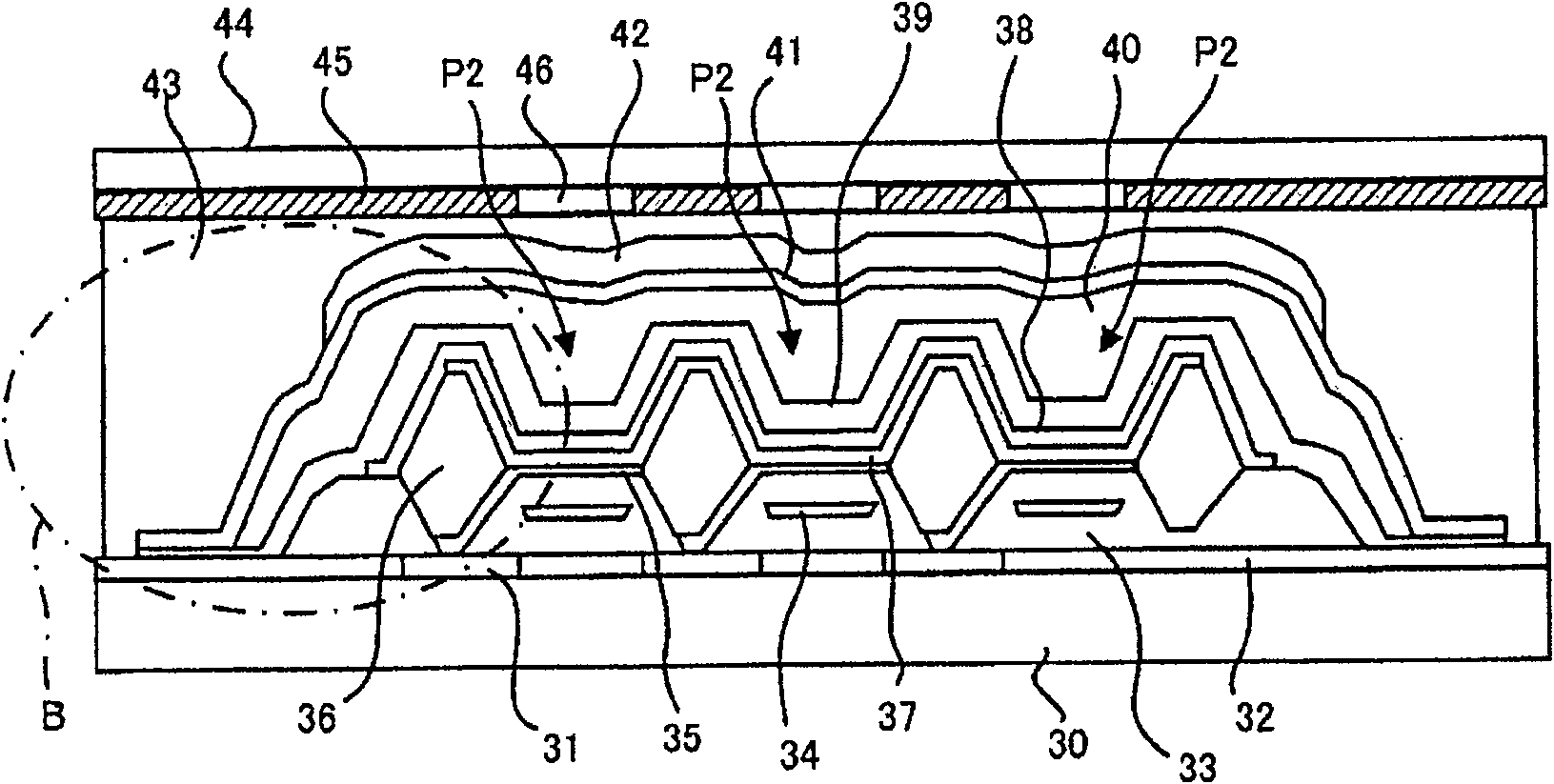
The organic EL panel according to the second embodiment of the present invention is a full-color panel using a low-molecular-weight organic EL material described later. This organic EL panel uses organic EL elements and color filters that emit white light. In addition, this organic EL element is of a top emission type in which light from the organic EL element is emitted from the side opposite to the main substrate.

[0042]

image 3 is a cross-sectional view of the organic EL panel, Figure 4 It is an enlarged cross-sectional view of the part B thereof. This organic EL panel includes a flat main substrate 30 . The main substrate 30 is formed of glass or plastic, and a plurality of organic EL elements P2 are formed thereon. The organic EL element P2 is an element that emits white light, and has an organic light-emitting layer 37 formed using a low-molecular-weight organic EL material described later. The inner luminescent layer) emits light.

[0043]

On the main su...


PUM


Abstract

A light-emitting device, comprising a plurality of organic EL elements (P1) arranged on a main substrate (10), an organic buffer layer (19) covering the plurality of organic EL elements (P1), and an organic buffer layer (19) disposed on the organic buffer layer (19). The first gas barrier layer 20 and the second gas barrier layer (21). The organic EL element (P1) emits light using an organic compound that emits light when excited by an electric field. On the main substrate (10), a step difference is provided by the organic EL element (P1). The organic buffer layer (19) is formed of organic compounds, the step difference on the organic buffer layer is smaller than the step difference on the cathode, and is roughly planarized. The region on the substrate (10) overlapping with the first gas barrier layer (20) formed by the inorganic compound and the region on the substrate (10) overlapping the second gas barrier layer (21) formed by the inorganic compound are not overlap exactly. Fully seal the light-emitting element with a gas barrier layer that is not prone to cracking or peeling.

Description

technical field [0001] The invention relates to a thin film sealing technology of a light-emitting element. Background technique [0002] As a light-emitting element, there is an organic EL (electro-luminescent) element that emits light using a light-emitting element having an organic light-emitting layer film composed of a multilayer organic light-emitting element that is sandwiched between two electrodes and excited by an electric field to emit light. Compound composition. In a manufacturing process including an organic EL element, sealing is performed to prevent the cathode, which includes an organic light-emitting material and an electron injection layer such as calcium, magnesium, and aluminum, from being deteriorated by outside air, moisture, or the like. As such a sealing technique, a sealing technique of covering an organic EL element with an extremely thin inorganic compound film is widely known (Patent Documents 1 to 4). In this technology, an inorganic compo...

Claims


Application Information

Patent Timeline
Patent Type & Authority Patents(China)
IPC IPC(8): H01L27/32H01L51/50H01L51/52H05B33/12H05B33/04
CPCH01L27/3244H01L27/3295H01L51/5237H10K59/38H10K59/122H10K59/12H10K50/8426H10K50/844H05B33/04
Inventor 林建二山内幸夫
Owner SEIKO EPSON CORP
Why Eureka
Try Eureka