Control system for modular robot based on CAN bus
A CAN bus and CAN controller technology, applied in the field of modular articulated robot control systems, can solve the problems of high cost, installation and maintenance costs, and achieve the effects of short development cycle, low cost and extended functions
- Summary
- Abstract
- Description
- Claims
- Application Information
AI Technical Summary
Problems solved by technology
Method used
Image
Examples
Embodiment Construction
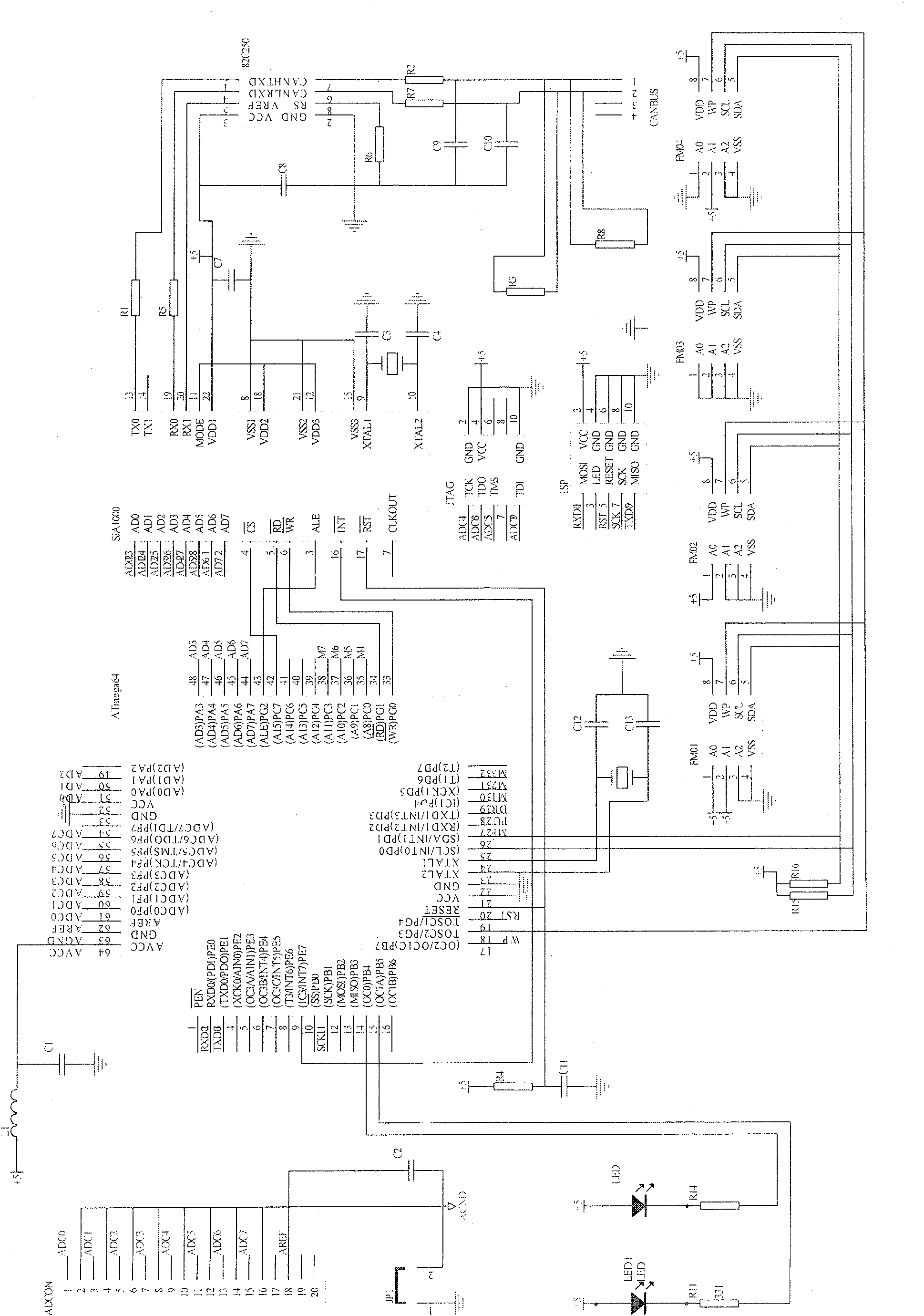
[0075] The circuit schematic diagram of the control module of the present invention is as shown in 2:
[0076] The main controller chip of the control module is ATmega64, which constitutes the communication interface circuit of the CAN bus with the CAN controller SJA1000 and the CAN bus driver PCA82C250; the pins 43, 42, 34, 33, 20, 9, 51, 50, 49 , 48, 47, 46, 45, 44 are respectively connected to pins 3, 4, 5, 6, 17, 16, 23, 24, 25, 26, 27, 28, 1, 2 of SJA1000; pin 13 of SJA1000 , 19, and 20 are connected to pins 1, 4, and 5 of PCA82C250 respectively; pins 7 and 6 of PCA82C250 are respectively connected to pins 1 and 2 of CANBAS through resistors R2 and R7; pins of four ferroelectric memories FM01-FM04 5, 6, and 7 are connected to pins 26, 25, and 18 of ATmega64 respectively; pins 1, 3, 5, and 9 of the JTAG interface are connected to pins 57, 55, 56, and 54 of ATmega64, as shown in Figure 3(b ) shown; the pins 1, 5, 7, and 9 of the ISP interface are connected to the pins 2, 2...
PUM
 Abstract
Description
Claims
Application Information
 - R&D
- Intellectual Property
- Life Sciences
- Materials
- Tech Scout
- Unparalleled Data Quality
- Higher Quality Content
- 60% Fewer Hallucinations
Browse by: Latest US Patents, China's latest patents, Technical Efficacy Thesaurus, Application Domain, Technology Topic, Popular Technical Reports.
© 2025 PatSnap. All rights reserved.Legal|Privacy policy|Modern Slavery Act Transparency Statement|Sitemap|About US| Contact US: help@patsnap.com


