Electric motor with brush holder and its assemblage method

一种组件、电刷装置的技术,应用在机电装置、电动组件、电路等方向,能够解决高速高功率电机不适用、电刷和换向器磨损、管道变形等问题

Inactive Publication Date: 2009-10-28
JOHNSON ELECTRIC SHENZHEN
View PDF5 Cites 0 Cited by
  • Summary
  • Abstract
  • Description
  • Claims
  • Application Information

AI Technical Summary

Problems solved by technology

If the inner diameter of the pipe is too small, the brush will not be able to slide; if the inner diameter is too large, the brush will shake in the pipe, causing instantaneous discharge of the commutator, resulting in rapid wear of the brush and commutator
Likewise, the holes in the insulator must be tightly controlled so that the pipe is properly gripped, but not so tight that the pipe deforms and catches the brushes
Another downside is that the snap fingers are not very resilient and usually don't spring back enough to keep the pipe in place
To overcome this problem, the groove for this finger is made relatively large to ensure the clearance between the finger and the groove, however, this will cause axial movement of the brush, which in turn will cause vibration under the effect of vibration. instantaneous discharge
[0005] Although some motors do not use brass brush boxes and allow the brushes to slide directly in the through holes in the bearing housing, this is not suitable for high speed and high power motors, where positioning and heat dissipation are extremely important issues

Method used


Image

  • Electric motor with brush holder and its assemblage method
  • Electric motor with brush holder and its assemblage method
  • Electric motor with brush holder and its assemblage method

Examples


Embodiment Construction

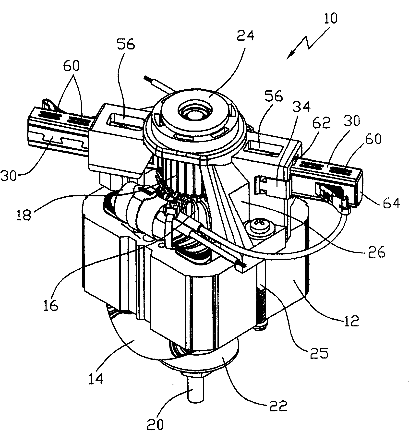
[0031] In the following, we will describe the figure 1 The invention is illustrated with reference to a preferred embodiment of a brush assembly for use in a general motor as shown. The general purpose electric machine 10 has a laminated stator core 12 supporting stator windings 14 . The wound rotor 16 includes a commutator 18 and a shaft 20 and is positioned extending through the stator core 12 . The output bearing housing 22 is fixed to one axial end of the stator core. The input bearing housing 24 is fixed to the other axial end of the stator core. The bearing blocks 22 , 24 are fixed to the stator core 12 by screws 25 , which here extend through the through holes of the bearing blocks 22 , 24 and pass through or flank the stator core 12 . Two bearing blocks 22, 24 support bearings in which the shaft 20 is journalled. The output bearing housing 22 is U-shaped and may include additional holes for mounting the motor to other equipment. The input bearing housing 24 is als...


PUM


Abstract

A universal motor has a brush cage assembly in which a U-shaped clip 34 is located about a wall of a through hole 28 of a bearing bracket 24 for receiving a brush cage 30. The clip 34 has an outer limb 42 with inwardly and rearwardly directed barbs 44 to grip an outer surface of the wall to prevent removal of the clip 34 and an inner limb 36 with outwardly and forwardly directed barbs 42 which resiliently deform as the cage 30 is inserted to snare the cage 30 should it move in the opposite direction. The clip 34 thus prevents withdrawal of the brush cage 30 and provides a lateral spring force against the cage 30 to reduce cage lateral position tolerance and movement.

Description

technical field [0001] The present invention relates to motors, and more particularly to brush holder assemblies for small motors. Background technique [0002] Many small brush motors, such as fractional horsepower general purpose motors and miniature DC motors, have brush boxes that direct the brushes into contact with the commutator. Typically such a brush box is basically a brass tube in which the brushes slide under the action of brush springs. The brush tubes are fixed to the motor structure to ensure accurate positioning of the contact points between the brushes and the commutator. Typically, the motor construction consists of a plastic or similar insulating material bearing housing into which a brass tube is pressed into a bore. Also, when the bearing housing is conductive, insulating bushings are used to secure the brass tube to the bearing housing. [0003] The brush tube requires means for fixing the brush tube in the hole of the insulator. Typically this is a...

Claims


Application Information

Patent Timeline
Patent Type & Authority Patents(China)
IPC IPC(8): H02K5/14H01R39/38H01R39/415H02K5/16H02K5/173H02K13/00
CPCH02K5/1732H01R39/385H02K5/148
Inventor 江浩然V·克雷斯塔尼
Owner JOHNSON ELECTRIC SHENZHEN
Why Eureka
Try Eureka