Two-shaft rotary pump with escape holes

a rotary pump and escape hole technology, applied in the direction of rotary/oscillating piston pump components, machines/engines, liquid fuel engines, etc., can solve the problems of unsatisfactory pump performance, unnecessary process, and badly influenced side clearance between the rotor and the end wall portion of the cylinder, so as to suppress the temperature rise of the pump and improve reliability and operation efficiency , the effect of reducing the side clearan

Active Publication Date: 2018-09-18
ORION MACH CO LTD
View PDF24 Cites 0 Cited by
  • Summary
  • Abstract
  • Description
  • Claims
  • Application Information

AI Technical Summary

Benefits of technology

[0031]The one example of the two-shaft rotary pump of the present invention is capable of improving reliability and operation efficiency by preventing an exhaust gas from flowing backward into a pump as much as possible, preventing the interior of the pump form being excessively compressed as much as possible, and suppressing temperature rise in the pump.
[0032]Another example of the two-shaft rotary pump of the present invention, in which a plurality of the rotors are provided in the axial direction of the rotating shafts, is capable of avoiding the bad influence of summing thermal expansions of the rotors, reducing the side clearances and suppressing the gas leakage, so that pump performance can be improved.

Problems solved by technology

Further, by providing the multistage rotors to the one rotating shaft, side clearances between the rotors and end wall portions of the cylinders are badly influenced by total thermal expansion of the rotors.
Namely, by the total thermal expansion of the rotors, it is difficult to suppress gas leakage by reducing the side clearances, so performance of the pump cannot be improved.
However, even in the ultimate operation, air leaking from a small gap is sucked, and a non-opened space (a closed space) has negative pressure, when the non-opened space formed by the rotor and the cylinder is communicated to the outside (a space whose pressure is higher than pressure of air discharged from the pump) via the gas outlet, so the exhaust air flows backward into the pump.
Namely, an unnecessary process is performed, so a power load must be enlarged and temperature in the pump must be increased.
Thus, by merely reducing the compressed space capacity immediately before exhaust opening so as to suppress the amount of the air flowing backward, a side opened to the air, in which an amount of the exhaust air is large (in case that the pressure of the sucked air is close to atmospheric pressure), is excessively compressed.
Further, reduction of a flow amount will be occurred by reduction of the capacity of the pump.
Note that, the backward flow of the gas is sure to be occurred as far as the capacity immediately before exhaust opening exists, so there is a problem that the above described problems must be reasonably de-escalated.
Conventionally, the problems have been solved by imposing a prescribed restriction on operating conditions, so it is difficult to improve operating efficiency.

Method used


Image

  • Two-shaft rotary pump with escape holes
  • Two-shaft rotary pump with escape holes
  • Two-shaft rotary pump with escape holes

Examples


Embodiment Construction

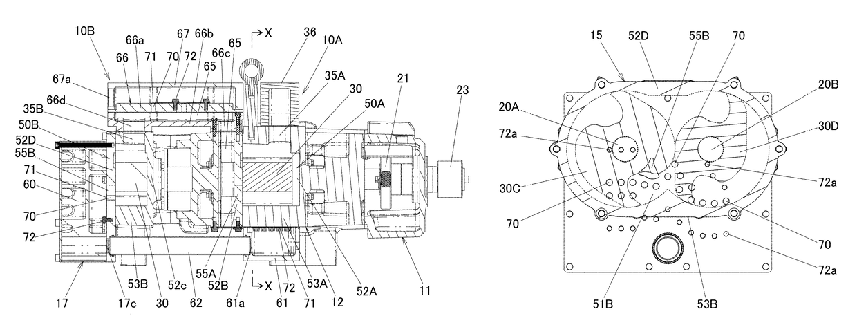
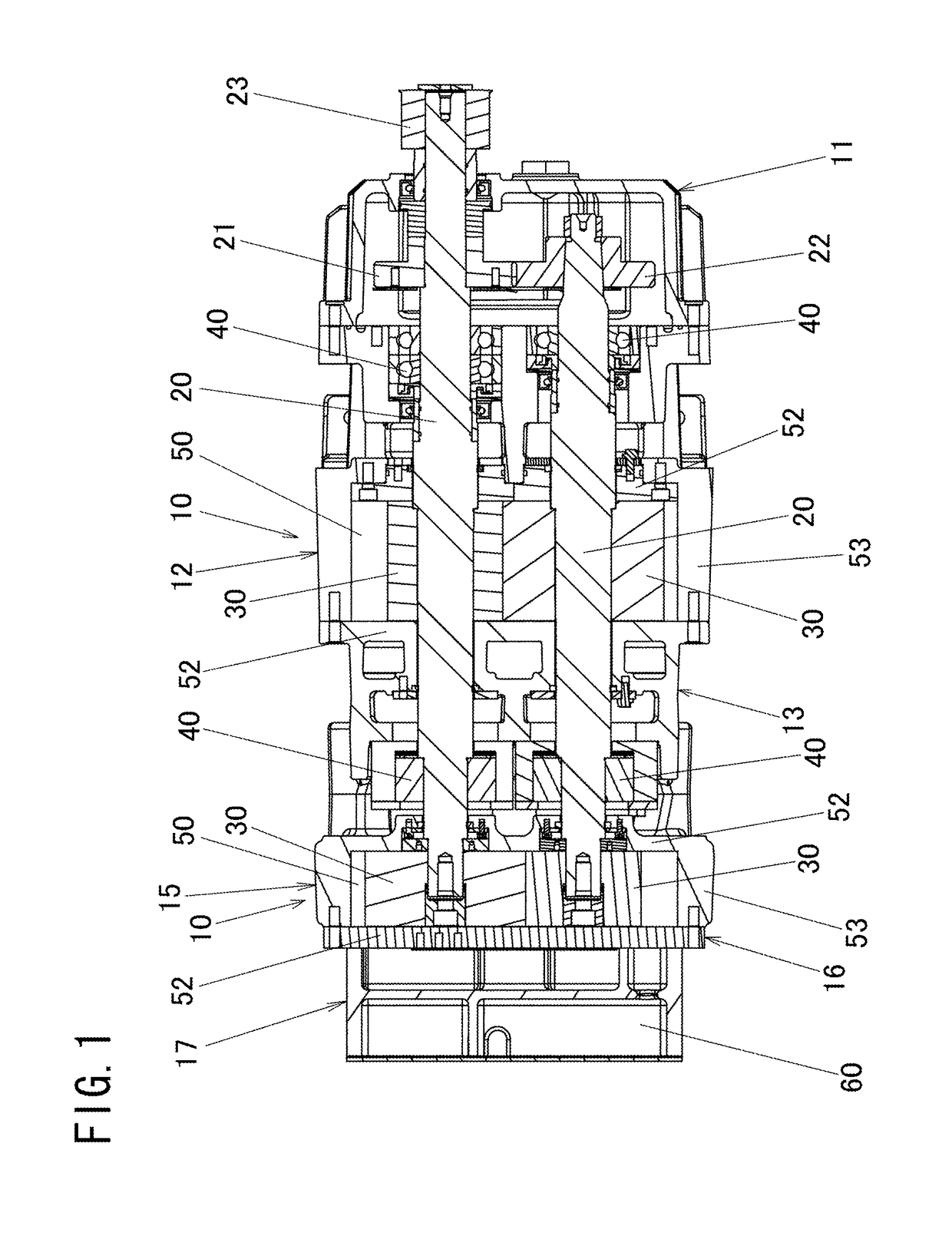
[0048]Embodiments of the present invention will now be explained with reference to the attached drawings. FIG. 1 is a sectional view, which shows an embodiment of the rotary pump relating to the present invention, as a generic concept, with symbols, and the generic concept of the present invention will be firstly explained with reference to FIG. 1.

[0049]Note that, the rotary pump of the present embodiment is a displacement pump belonging to a two-shaft rotary pump. Two-shaft rotary pumps include, for example, a claw pump of a rotor contactless type pump, a screw pump, a roots pump, etc. One-shaft rotary pumps include, for example, a vane pump, etc. Each of the rotary pumps is actuated by, for example, an electric motor and used as a pneumatic device, e.g., a vacuum pump, a blower.

[0050]In the two-shaft rotary pump of the present embodiment, two rotating shafts 20 and 20 provided with rotors 30 and 30 are supported by bearings 40 and 40, such that the two rotors 30 and 30 are rotated...


PUM


Abstract

Provided is a two-shaft rotary pump which is capable of improving reliability and operation efficiency by preventing an exhaust gas from flowing backward into a pump as much as possible, preventing the interior of the pump form being excessively compressed as much as possible, and suppressing temperature rise in the pump. A two-shaft rotary pump in which two rotating shafts (20, 20) provided with rotors (30, 30) are supported by bearings, such that the two rotors (30, 30) are rotated in a noncontact manner with a small clearance kept therebetween and the two rotors (30, 30) are rotated in a noncontact manner with a small clearance between an inner surface of a cylinder (50) and the two rotors, and a gas sucked into the cylinder (50) and compressed is discharged from the cylinder (50), wherein an escape hole capable of letting a part of the compressed gas escape is provided in at least one of end wall portions (52) constituting both ends of the cylinder (50) and opened in the axial direction of the rotating shafts (20, 20).

Description

FIELD OF TECHNOLOGY[0001]The present invention relates to a two-shaft rotary pump, in which two rotating shafts provided with rotors are supported by bearings, such that the two rotors are rotated in a noncontact manner with a small clearance kept therebetween and the two rotors are rotated in a noncontact manner with a small clearance between an inner surface of a cylinder and the two rotors, and a gas sucked into the cylinder and compressed is discharged from the cylinderBACKGROUND TECHNOLOGY[0002]A noncontact type vacuum pump equipped with claw rotors is an example of a two-shaft rotary pump. For example, in an exhaust structure of a claw pump and a method of exhausting a gas which were proposed by the applicant of the present application, the pump comprises: a cylinder forming a pump chamber; one side plate and the other side plate covering end faces of the cylinder; two rotating shafts being arranged in parallel in the cylinder, the rotating shafts being rotated in opposite dir...

Claims


Application Information

Patent Timeline
Patent Type & Authority Patents(United States)
IPC IPC(8): F04C28/24F04C28/02F04C23/00F04C18/12F04C28/26F04C25/02F04C29/06
CPCF04C28/24F04C18/123F04C23/001F04C25/02F04C28/26F04C29/065F04C28/02F04C2270/17F04C2240/51
Inventor YOSHIDA, YOSUKEHARAYAMA, SHINGOMIYAZAWA, SHUNYAMADA, HUMIHIKO
Owner ORION MACH CO LTD
Why Eureka
Try Eureka