Magnetic flow switch, for aspirators in particular

A flow switch, magnetic flow technology, applied in magnetic/electric field switches, electric switches, grinding/polishing safety devices, etc., can solve problems such as hindering spring operation, damage, wear, etc.

Inactive Publication Date: 2009-11-04
圭多・瓦伦蒂尼
View PDF4 Cites 0 Cited by
  • Summary
  • Abstract
  • Description
  • Claims
  • Application Information

AI Technical Summary

Problems solved by technology

[0007] Nevertheless, it must be taken into account that the fluid flow through the chamber of the flow switch (especially in the case of a suction device) may introduce impurities that tend to hinder the operation of the spring, as well as the risk of causing its damage and wear

Method used


Image

  • Magnetic flow switch, for aspirators in particular
  • Magnetic flow switch, for aspirators in particular
  • Magnetic flow switch, for aspirators in particular

Examples


Embodiment Construction

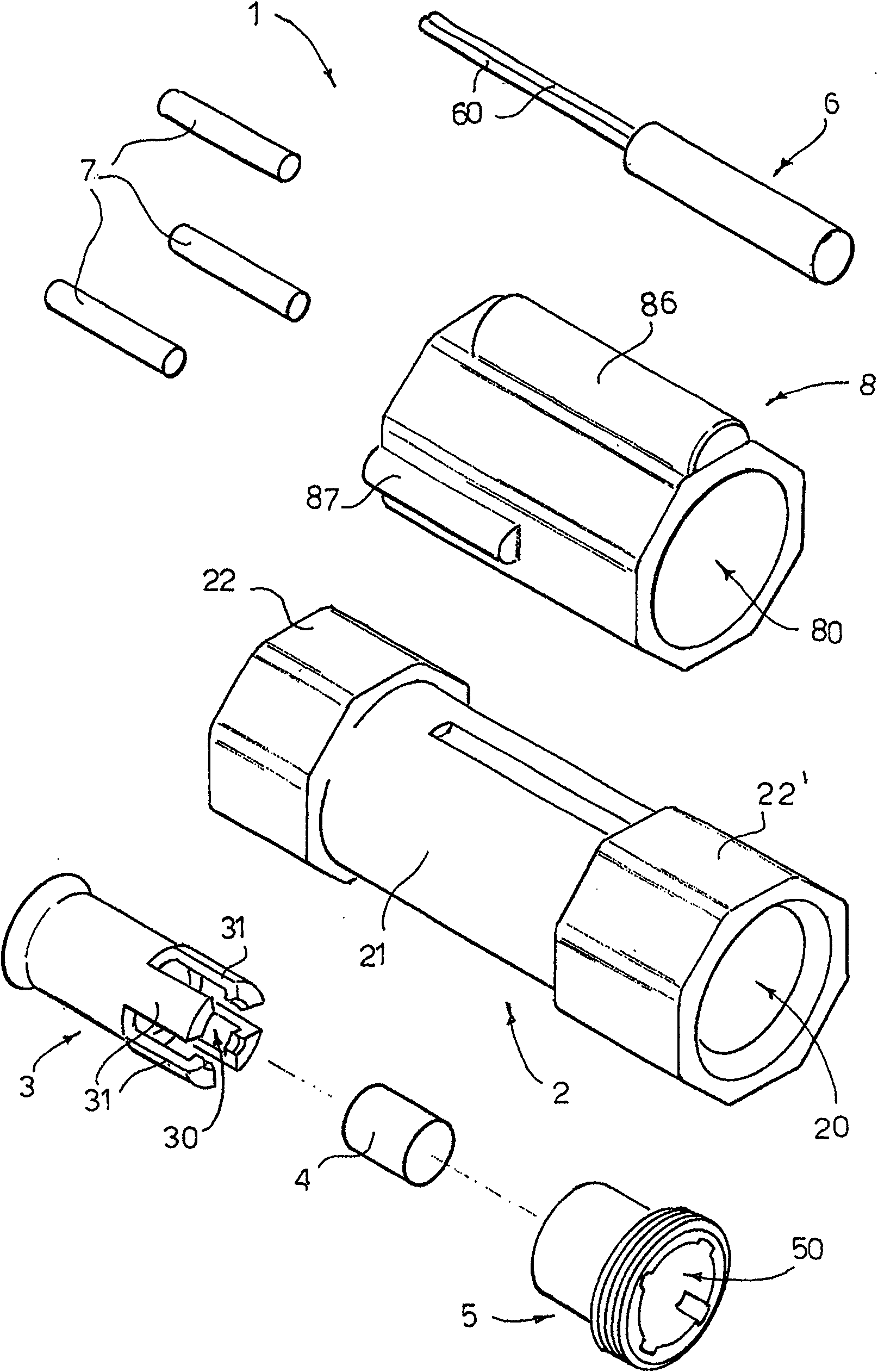
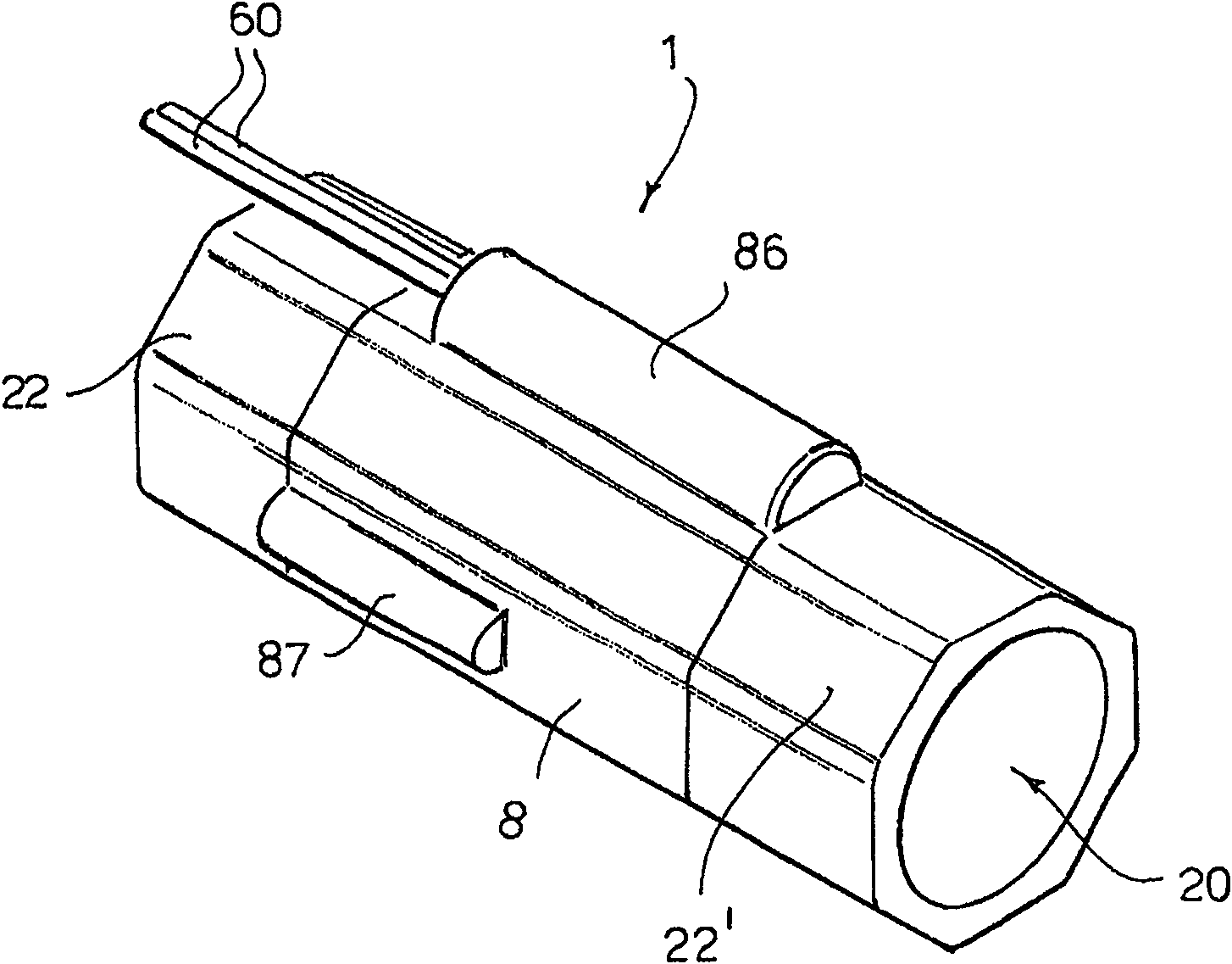
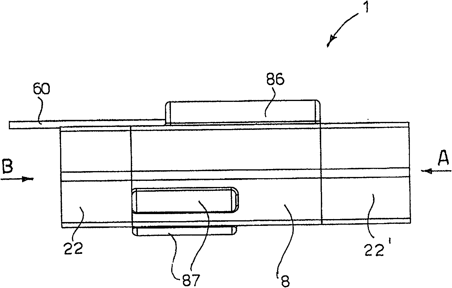
[0031] According to the flow switch of the present invention, the whole is indicated by the reference numeral 1, which will be Figure 1~7 Described with the help of.

[0032] The flow switch 1 includes a main body 2 with a hollow inside, and is provided with a substantially cylindrical axially penetrating chamber 20. The main body 2 of the flow switch includes a middle portion 21 having a cylindrical outer side between two ends 22 and 22', wherein the two ends have a hexagonal nut shape suitable for engagement with a type "20" hexagonal wrench . The hexagonal shape of the ends 22, 22' is specially selected so that the flow switch 1 can be accommodated in a suction device commonly available on the market.

[0033] For the sake of clarity, the hexagonal portion at the front end (i.e., the fluid inlet portion) is denoted by reference numeral 22, and the hexagonal portion at the rear end (i.e., the fluid outlet portion) is denoted by reference numeral 22'. In this way, in the followin...


PUM


Abstract

A magnetic flow switch (1) is described that includes a body (2) defining a chamber (20) destined to have a fluid flow pass through it, an excitation magnet (4) placed in a shuttle (3) mounted such that it can slide within the chamber (20) of the body to pass from an initial front position to a final rear position, a Reed switch (6) arranged on the body (2) of the flow switch to detect the magnetic field generated by the displacement of the excitation magnet (4) and to accordingly send a control signal to an electronic control board, and at least one attraction magnet (7) arranged on the body (2) of the flow switch, in a position such as to generate an attraction magnetic field able to attract the excitation magnet (4) to make the shuttle (3) move to the initial front position.

Description

Technical field [0001] The present invention relates to a magnetic flow switch, which is particularly suitable for being applied to a suction device so that it can be automatically activated when it is activated by, for example, a pneumatic machine (such as a grinder) connected to the suction device. Background technique [0002] Pneumatic grinders connected to a suction device (equipped with a suction turbine for sucking the dust generated during the grinding process) via a suction pipe are very common in the market. There are known a variety of valve switches, usually called flow switches, which are used to switch on and thereby control the suction of the suction device. [0003] The flow switch can sense the flow of fluid through its valve body, and accordingly send out electrical control signals to control the connection of the suction device. To this end, the flow switch includes a magnet that can be installed in its body in a freely sliding manner. The magnet is moved by th...

Claims


Application Information

Patent Timeline
Patent Type & Authority Patents(China)
IPC IPC(8): H01H35/24H01H36/00
CPCB24B23/026H01H35/405B24B55/10
Inventor 圭多·瓦伦蒂尼
Owner 圭多・瓦伦蒂尼
Why Eureka
Try Eureka