Magnetic flow switch, for aspirators in particular

A technology of flow switch and magnetic flow, which is applied in the direction of magnetic/electric field switch, electric switch, grinding/polishing safety device, etc., and can solve problems such as wear, damage, and hindering spring operation

Inactive Publication Date: 2006-06-28
圭多・瓦伦蒂尼
View PDF0 Cites 4 Cited by
  • Summary
  • Abstract
  • Description
  • Claims
  • Application Information

AI Technical Summary

Problems solved by technology

[0007] Nevertheless, it must be taken into account that the fluid flow through the chamber of the flow switch (especially in the case of a

Method used


Image

  • Magnetic flow switch, for aspirators in particular
  • Magnetic flow switch, for aspirators in particular
  • Magnetic flow switch, for aspirators in particular

Examples


Embodiment Construction

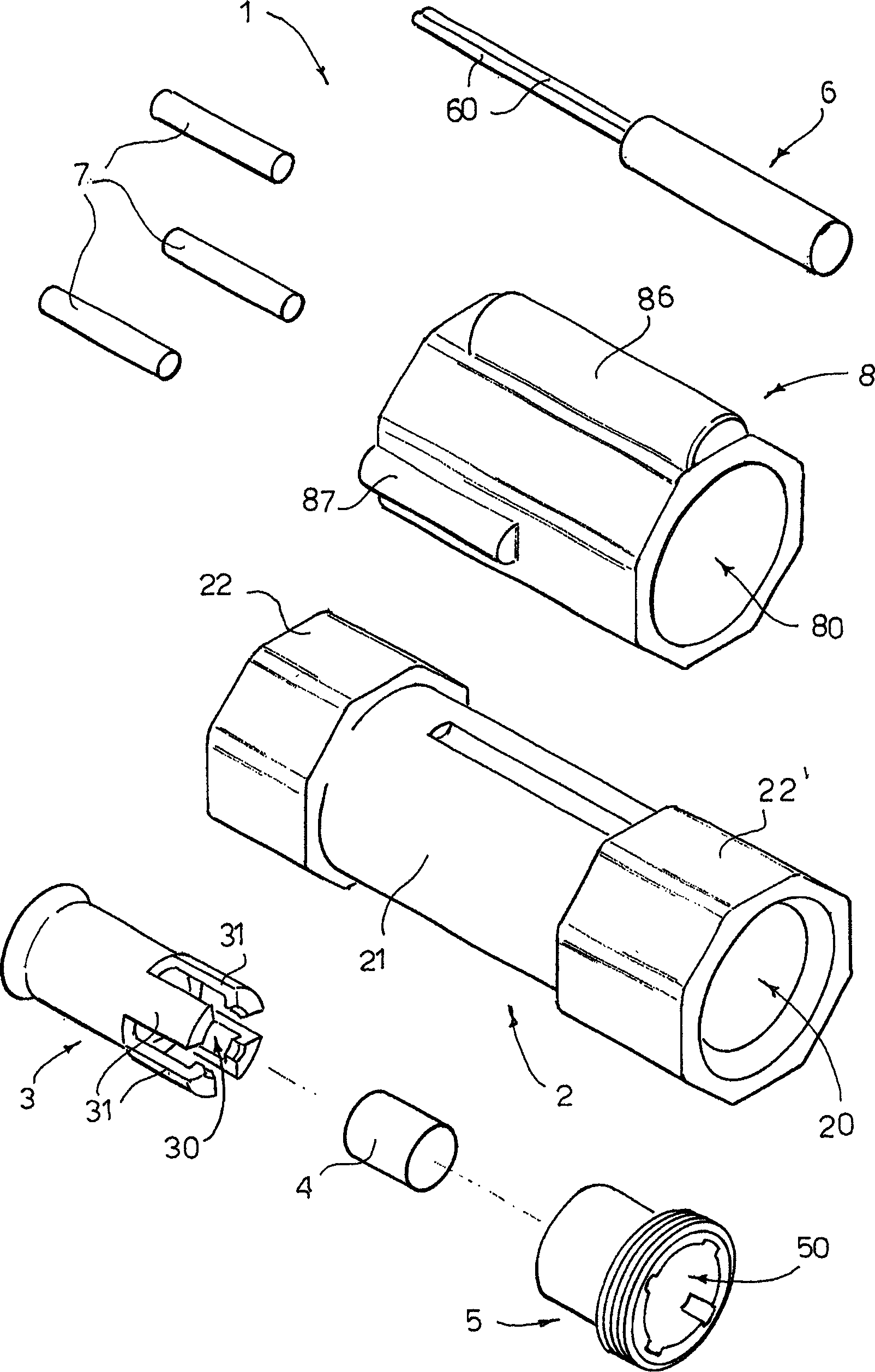
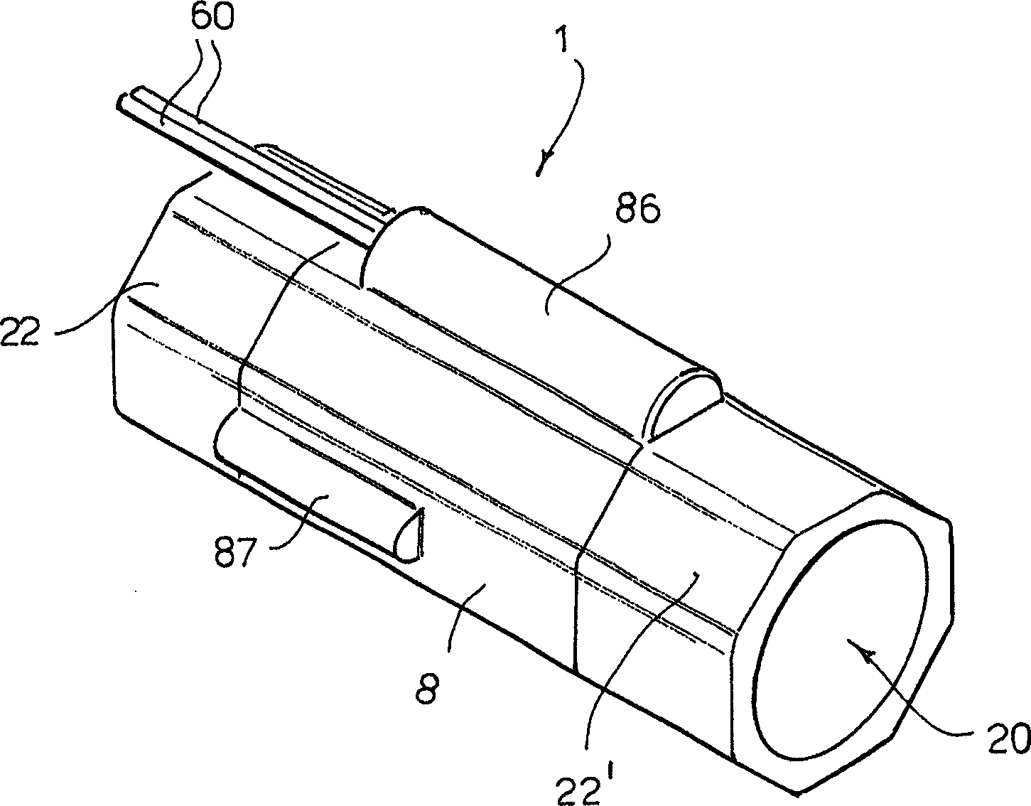
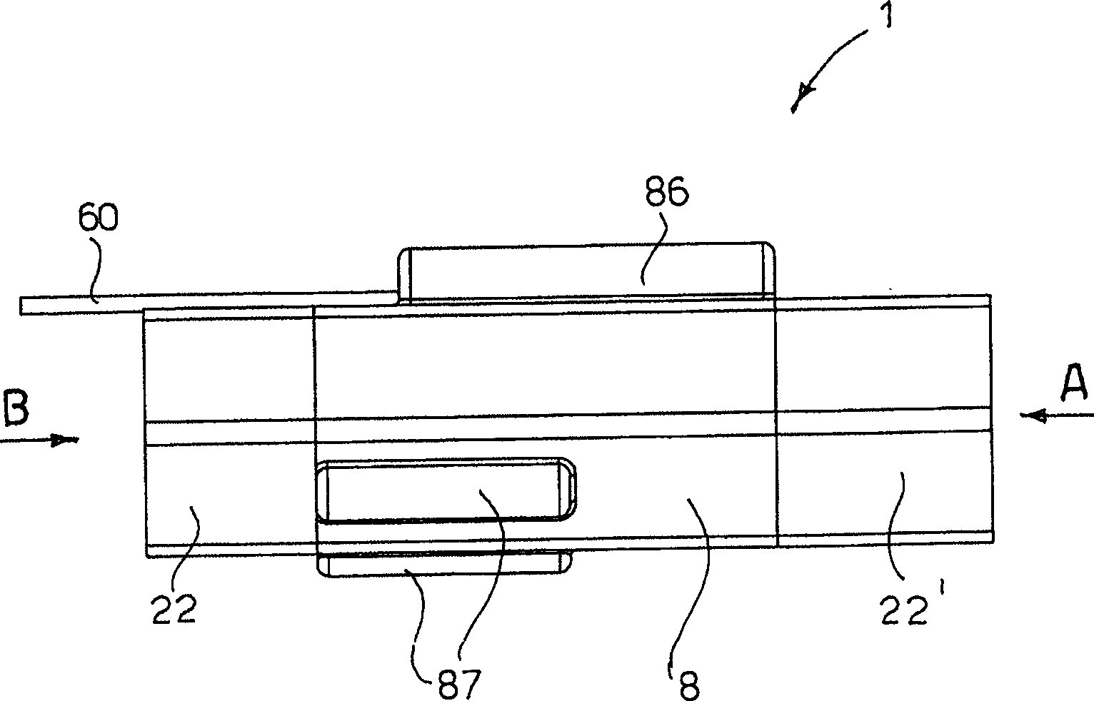
[0031] The flow switch according to the present invention, represented as a whole by the reference numeral 1, will be Figures 1 to 7 described with the help of .

[0032] The flow switch 1 comprises an internally hollow body 2 provided with a substantially cylindrical axially penetrating chamber 20 . The body 2 of the flow switch comprises a middle part 21 with a cylindrical outer side between two ends 22 and 22', wherein the two ends have the shape of a hexagon nut adapted to engage with a hexagon wrench of type "20" . The hexagonal shape of the ends 22, 22' is specially chosen so that the flow switch 1 can be accommodated in a suction device commonly available on the market.

[0033] For clarity, the hexagonal portion of the front end (ie the fluid inlet portion) is designated by the reference numeral 22, and the hexagonal portion of the rear end (ie the fluid outlet portion) is designated by the reference numeral 22'. Thus, in the following, the terms "front end" a...


PUM


Abstract

The invention describes a magnetic flow switch (1) comprising: a body (2) defining a chamber (20) for the passage of a fluid flow; an exciter (4) arranged in the shuttle body, The shuttle body is mounted to slide from an initial front position to a final rear position in the chamber of the main body; a reed switch (6) is provided on the main body (2) of the flow switch to detect the movement by the exciter ( 4) The magnetic field generated by the displacement, and correspondingly sends a control signal to the electronic control board; and, at least one attracting magnet (7) is arranged at a position on the main body (2) of the flow switch, thereby generating a magnetic field capable of attracting the exciter The attractive magnetic field of (4) moves the shuttle body (3) to the initial front position.

Description

technical field [0001] The present invention relates to a magnetic flow switch, particularly suitable for application to a suction device, such that it can be automatically activated when activated, for example, by a pneumatic machine (eg a grinder) connected to the suction device. Background technique [0002] Pneumatic grinders connected via a suction pipe to a suction device equipped with a suction turbine for sucking in the dust generated during the grinding process are common on the market. Various valve switches, commonly referred to as flow switches, are known for controlling the switching on and thus the suction of suction devices. [0003] The flow switch is capable of sensing the flow of fluid through its valve body and correspondingly issuing an electrical control signal to control the switching on of the suction device. For this purpose, the flow switch includes a magnet that can be freely slid within its body. The magnet is moved by the flow of fluid through t...

Claims


Application Information

Patent Timeline
IPC IPC(8): H01H35/24H01H36/00
CPCB24B23/026B24B55/10H01H35/405
Inventor 圭多·瓦伦蒂尼
Owner 圭多・瓦伦蒂尼
Why Eureka
Try Eureka