
Hardware board backboard interface

A hardware board and backplane technology, applied in the field of communication, can solve problems such as increasing the workload of post-debugging, failing to achieve the desired effect, and unable to ensure reliable data reception, etc., to achieve consistent delay, consistency, and reliable reception The effect of data

Active Publication Date: 2009-12-16
ZTE CORP
View PDF3 Cites 0 Cited by
  • Summary
  • Abstract
  • Description
  • Claims
  • Application Information

AI Technical Summary

Problems solved by technology

Using this method not only greatly increases the workload of post-debugging, but also in actual application, the transmission delay changes due to differences in circuit board processing batches and design modifications, and the test delay is adjusted at the receiving end method will not guarantee reliable reception of data under all conditions
So, the above solution did not achieve the desired effect

Method used


Image

  • Hardware board backboard interface
  • Hardware board backboard interface
  • Hardware board backboard interface

Examples


Embodiment Construction

[0019] Various preferred embodiments of the present invention will be described in detail below.

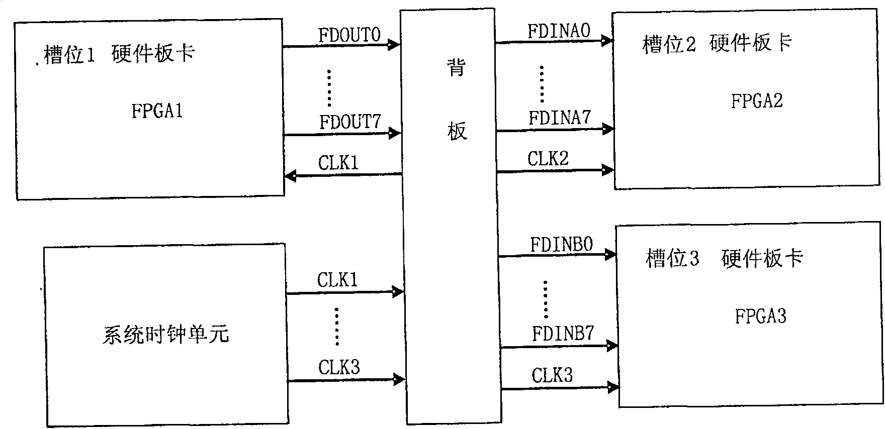
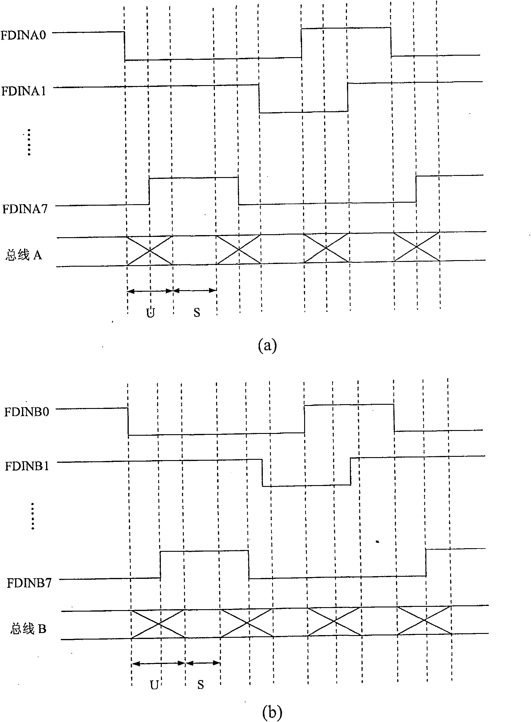
[0020] The design idea of ​​the present invention is to add two sets of sending and receiving triggers on the backplane side of the hardware board, and these two sets of triggers will cut the time delay from the sending end to the receiving end, so that the time delay will not accumulate, and the system timing During the design, we only need to pay attention to the reliability of the transceiver trigger and the delay of the backplane, and the delay coordination of the own devices on the hardware board is controlled by the hardware board. By adopting this design method, the data delay fluctuation range from the sending end to the receiving end can be reduced, and the system synchronization design becomes easy to realize, thus providing a simple structure, easy to implement, Effective backplane interface with low cost and guaranteed data transmission quality, see below Figure 4 B...


PUM


Abstract

The invention discloses a backplane interface of a hardware board, which is located on the hardware board, and the business data processing unit of the hardware board transmits business data through the backplane interface and the backplane, and is characterized in that the backplane The board interface includes: a set of sending triggers, used to send the business data pre-sent by the hardware board to the backplane; and a set of receiving triggers, used to collect and receive data from the backplane, and send it to the business of the hardware board data processing unit. The present invention cuts the time delay from the sending end to the receiving end by adding two groups of flip-flops, so that the time delay does not accumulate, and only needs to pay attention to the reliability of the sending and receiving flip-flops and the backplane time delay when designing the system timing sequence.

Description

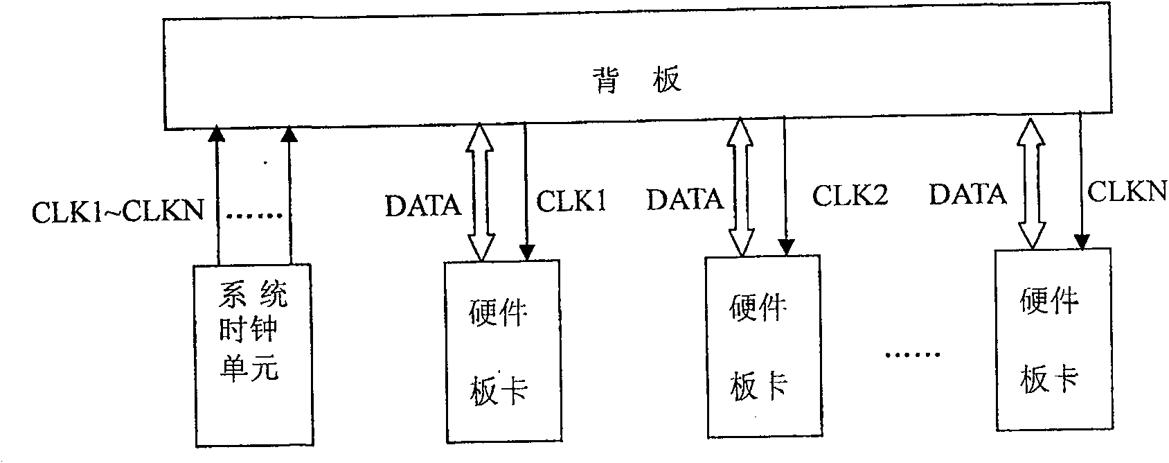
technical field [0001] The invention relates to the field of communication, in particular to a design scheme of a backplane interface capable of eliminating the correlation of slots of hardware boards. Background technique [0002] In the communication field, switches, routers, and various transmission equipment usually adopt a chassis system structure with multiple interface card slots. The hardware boards in each slot are connected to the backplane through the backplane socket interface, so the connection between each hardware board The data information can be transmitted through the backplane bus, and its principle structure is as follows: figure 1 shown. In the process of data transmission, the hardware boards of each slot share the same clock source, and the in-phase clock sent by the system clock unit (the system clock CLK1, CLK2, ... CLKN) to complete the sending and receiving of data. [0003] When the device adopts figure 1 In the system structure shown, if the ...

Claims


Application Information

Patent Timeline
Patent Type & Authority Patents(China)
IPC IPC(8): G06F13/40
Inventor 柯楚石鸿斌
Owner ZTE CORP
Learn More