Oil smoke removing and discharging clean-up machine

A purifier, oil fume technology, applied in the direction of oil fume removal, chemical instruments and methods, household heating, etc., can solve the problems of long suction pipeline, affecting suction force, large resistance of cyclone separation pipe, etc., and achieve suction capacity Improve and improve the suction effect and ensure the effect of normal operation

Active Publication Date: 2009-12-23
溧阳常大技术转移中心有限公司
View PDF16 Cites 4 Cited by
  • Summary
  • Abstract
  • Description
  • Claims
  • Application Information

AI Technical Summary

Problems solved by technology

The swirl tube of patent CN01120562.8 has a spiral channel inside, and the structure is complex, and oil accumulates in the tube after a long time, and the patent does not propose a suction and discharge scheme, which is difficult to implement
Patent CN92102246.8 and patent 91108847.4 are split type of fan and swirl tube, the suction pipeline is long, the loss of vacuum degree is large, and the suction force is affected
[0006] Another patent, application number 200610039320.3, is an oil fume separator, in which the cyclone separation tube has a large resistance and is a single inlet, and the flow field in the cyclone separation tube has poor symmetry, which affects the separation and purification effect

Method used


Image

  • Oil smoke removing and discharging clean-up machine
  • Oil smoke removing and discharging clean-up machine
  • Oil smoke removing and discharging clean-up machine

Examples


Embodiment Construction

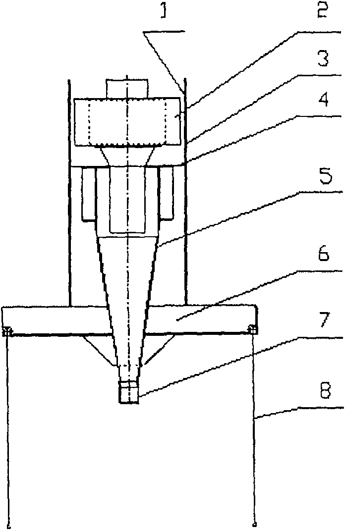
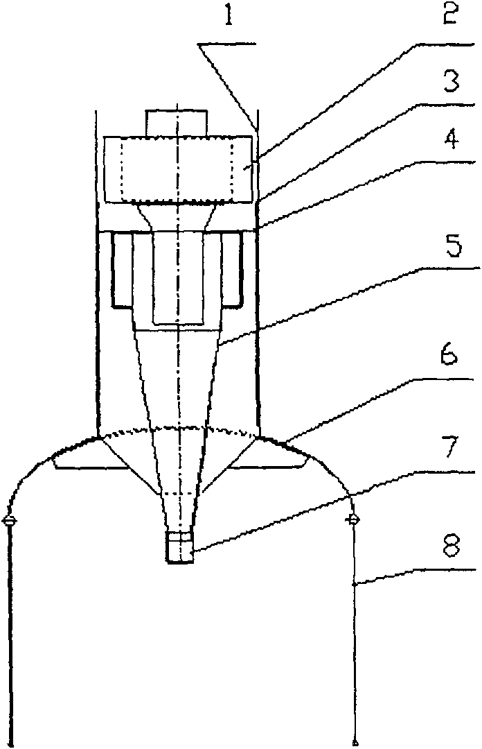
[0028] The embodiments of the present invention will be described below in conjunction with the drawings.

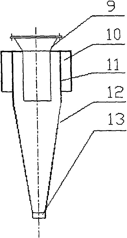
[0029] The composition of the oil fume removal and purification machine given in this example is as follows figure 1 or figure 2 Shown. The oil fume removal and exhaust purification machine includes an outer cylinder (1), a fan (2), an inner cylinder (3), a partition (4), one or more cyclone separation tubes (5), a fume hood (6), a collector The oil cup (7) and the roller shutter (8), in which the cyclone separation pipe has two or more symmetrical inlets, are vertically installed in the circular inner cylinder. The air outlet (9) of the cyclone separation pipe is connected with the inlet of the upper fan (2); the top of the cyclone separation pipe (5) is provided with a partition (4), which is connected to the outer wall of the cyclone separation pipe and the inner cylinder (3) An oil fume annular tornado suction channel is formed; the lower part of the cyclone separation...


PUM

PropertyMeasurementUnit
diameteraaaaaaaaaa

Abstract

The invention relates to a method and equipment for removing and purifying oily fume, which is composed of one or more cyclone separation pipes, fans, inner cylinders, outer cylinders, partitions, fume hoods, rolling shutters and oil collection cups. Among them, the cyclone separation pipe has two or more symmetrical inlets and is vertically installed in the inner cylinder. The separator, the outer wall and the inner cylinder of the cyclone separation tube form an oil fume annular tornado suction channel. The fan is installed on the top of the cyclone separation tube. The inlet of the fan is connected with the outlet of the cyclone separation pipe. The lower part of the cyclone separation pipe stretches out to the bottom of the smoke hood, and the oil discharge port at the bottom is covered with an oil collecting cup. The present invention is based on the aerodynamic design, so that the oil fume flows smoothly, the resistance is small, the suction and purification efficiency is high, and the medium-free separation is adopted, never blocked, and the high-efficiency work of the range hood can be continuously ensured.

Description

Technical field [0001] The invention relates to a method and equipment for removing and purifying oil fume. Background technique [0002] At present, the range hoods on the market are basically impeller-type suction and inertial separation of oil droplets in the cooking fume. The installation height, that is, the distance between the suction port and the stove surface is generally 600-750mm. [0003] Since the suction wind speed outside the suction port has a strong attenuation characteristic, when the suction port wind speed is 20m / s, the effective suction distance is only twice the suction port diameter. For the existing range hood, if the diameter of the suction port is 200mm and the suction wind speed is 4m / s, the effective suction distance is less than 200mm. In order to improve the suction effect, generally use your brain on the installation height of the hood and range hood. For example, the front panel of the hood of patent CN200510024074.X is made of transparent material...

Claims


Application Information

Patent Timeline
Patent Type & Authority Patents(China)
IPC IPC(8): F24C15/20B01D45/16
Inventor 袁惠新
Owner 溧阳常大技术转移中心有限公司
Why Eureka
Try Eureka