
Electronically controlled memory type fault indicating apparatus

A technology of fault indication and electronic control, applied in the direction of measuring devices, measuring electricity, measuring electrical variables, etc., can solve the problems of fewer fault types, indication maintenance, and indication disappearance, and achieve unique and novel effects

Active Publication Date: 2010-01-13
SEARI ELECTRIC TECH
View PDF8 Cites 0 Cited by
  • Summary
  • Abstract
  • Description
  • Claims
  • Application Information

AI Technical Summary

Problems solved by technology

1) It uses displayable electronic components to emit light to indicate the corresponding fault. The advantage of this method is that the indication is clear and multiple faults can be distinguished. The disadvantage is that the indication disappears after the power is turned off; 2). Corresponding indication marks are exposed on the viewing window to distinguish faults, such as patent CN1429396, the advantage of this method is that the indication remains after power off, and the disadvantage is that due to the limitation of the mechanical structure, there are fewer fault types displayed

Method used


Image

  • Electronically controlled memory type fault indicating apparatus
  • Electronically controlled memory type fault indicating apparatus
  • Electronically controlled memory type fault indicating apparatus

Examples


Embodiment Construction

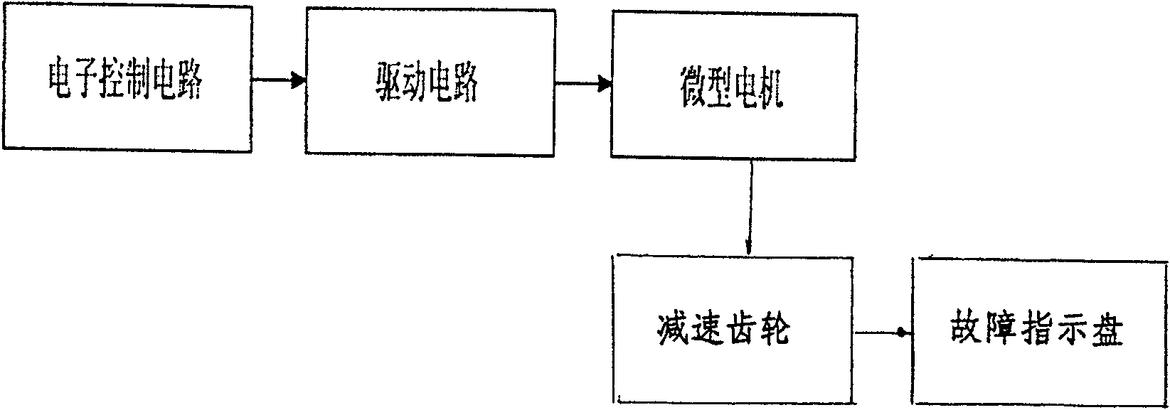
[0021] refer to figure 1 , which is a functional block diagram of the electronically controlled memory fault indicating device of the present invention.

[0022] The electronic control circuit 1 controls the signal output to the driving circuit 2, and controls the on-off of the circuit.

[0023] The driving circuit 2 amplifies the signal to provide driving energy for the micro motor 3 .

[0024] The micro motor 3 converts electrical energy into mechanical energy to form a rotating action.

[0025] The reduction gear 4 converts the rotation speed of the micro-motor 3 into a specific rotation speed output.

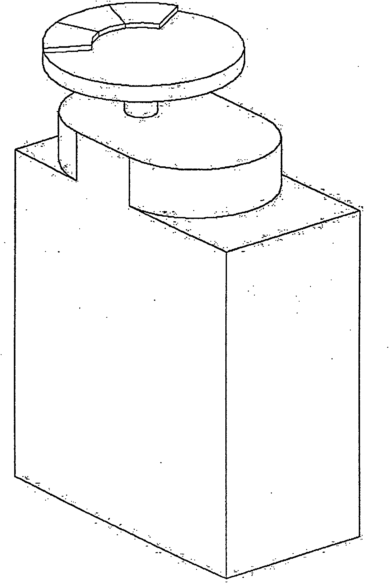
[0026] The fault indication plate 5 rotates following the gear shaft 4, and has different display intervals on its upper surface, and indicates different faults by displaying different intervals.

[0027] Signal transmission between the above circuits: the control signal is output to the drive circuit through the electronic control circuit, and the drive circuit outputs t...


PUM


Abstract

This invention relates to one electron control memory fault indication device, which comprises electron control circuit, driver circuit, micro motor, and deceleration gear and fault indication panel, wherein control signal outputs electron control circuit to driver circuit; driver circuit outputs the amplified driver electrical signal into micro motor to convert electricity energy into mechanic energy to output rotation operation and into special rotation output through deceleration gear to drive fault indication panel to relative fault indication area and to stop move; the said fault indication panel is on break of electron control circuit to keep original fault indication output.

Description

technical field [0001] The invention relates to an electronically controlled memory-type fault indicating device, which includes an electronic control circuit, a drive circuit, a micro motor, a reduction gear and a fault indicating plate, and belongs to the field of electric technology. Background technique [0002] The fault indication device is one of the indispensable parts of the switchgear in low-voltage electrical appliances. It is responsible for indicating fault information, including fault category and fault cause. [0003] The fault indication device in the switchgear can change the indication information immediately after the fault occurs, and when the fault occurs and the switch trips, the fault indication device can effectively keep the indication content unchanged, so that the maintenance personnel can identify the record. [0004] At present, there are mainly two ways to realize the fault indication device in the switch electrical appliances at home and abroad...

Claims


Application Information

Patent Timeline
Patent Type & Authority Patents(China)
IPC IPC(8): G01R31/02G01R31/327
Inventor 朱文灏邵福山曾萍
Owner SEARI ELECTRIC TECH
Learn More