Special gear rack machining lathe

A technology for special lathes and racks, which is applied in metal processing, metal processing equipment, metal processing machinery parts, etc. It can solve the problems affecting the use of racks and different spacing, and achieve the effect of improving processing accuracy and reducing errors

Inactive Publication Date: 2010-02-03
太仓市骏马机械设备有限公司
View PDF5 Cites 0 Cited by
  • Summary
  • Abstract
  • Description
  • Claims
  • Application Information

AI Technical Summary

Problems solved by technology

[0002] In the prior art, the processing method of the rack uses milling cutters of different standards to directly grind the raw materials. For the rack with small modulus, this processing is relatively simple and convenient; but when the modulus of the rack increases , it is not suitable to use the milling cutter to directly grind into teeth, so people usually use a planer to plan the rack blank by planing, but no matter whether the milling cutter is used to process the small modulus rack or the planer is used to process the large modulus rack , during the processing, the teeth on each rack blank are processed one by one, so that after the processing is completed, the spacing between each tooth will be different, which will affect the use of the rack

Method used


Image

  • Special gear rack machining lathe
  • Special gear rack machining lathe
  • Special gear rack machining lathe

Examples


Embodiment Construction

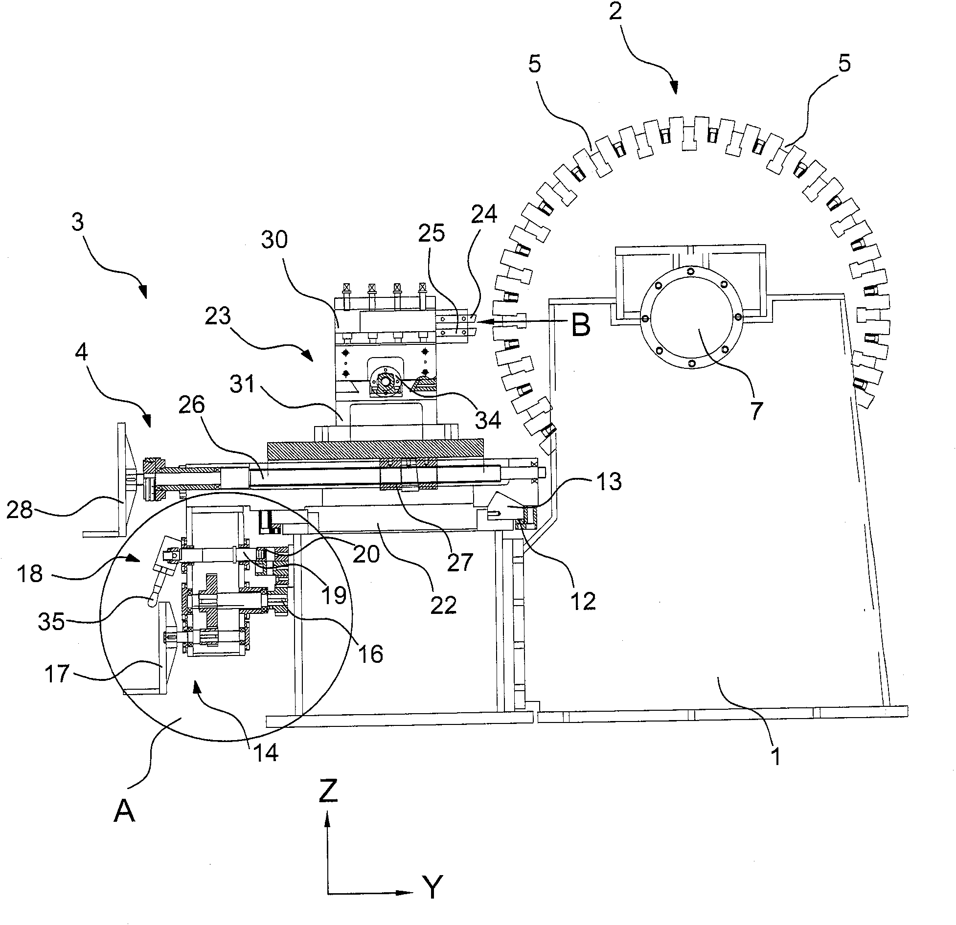
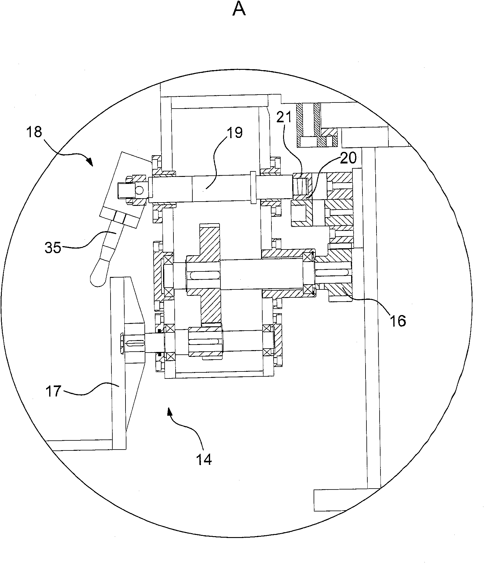
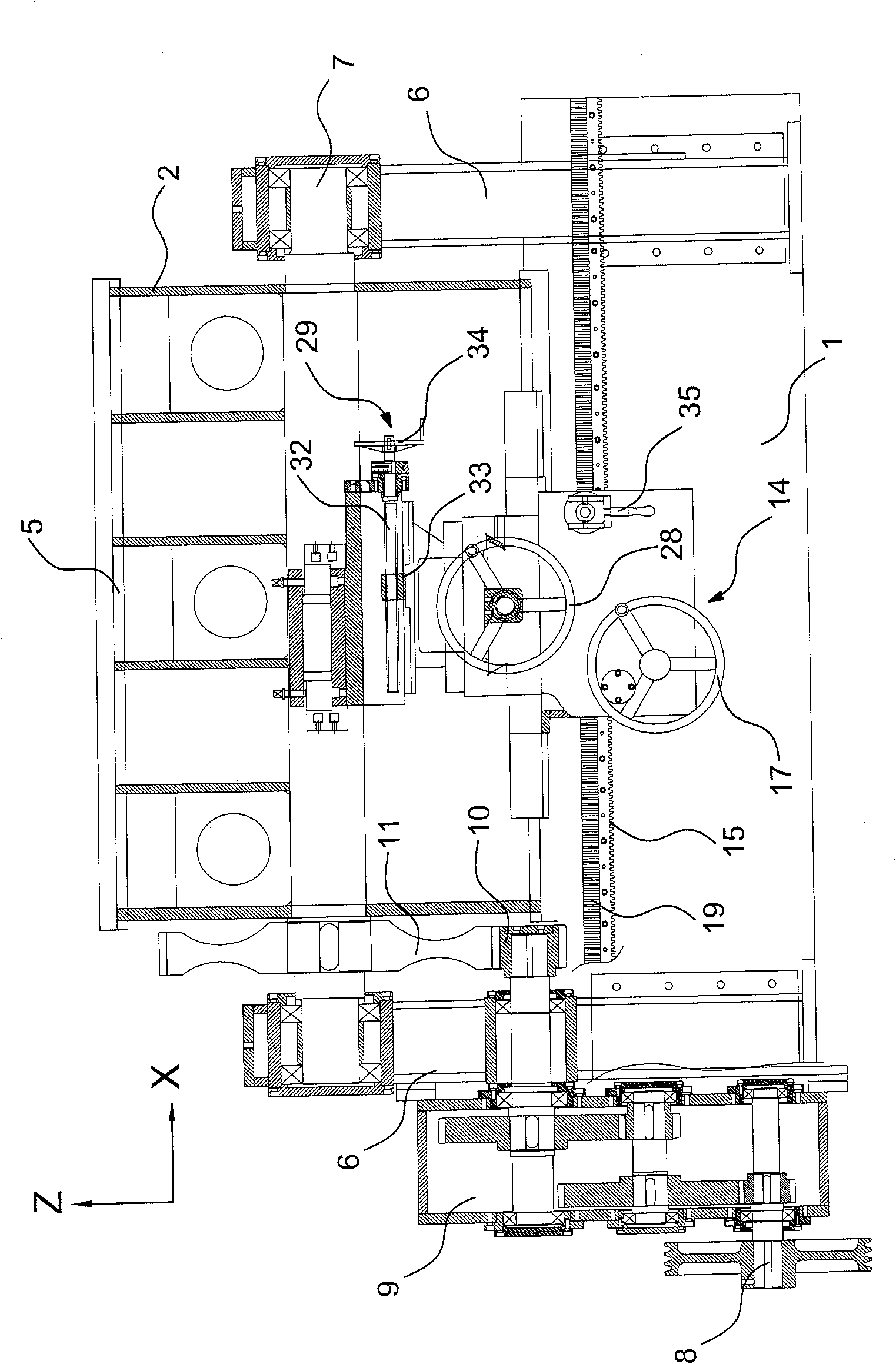
[0017] See figure 1 As shown in ~5, a special lathe for processing racks, it includes a machine bed 1, a worktable 2 set on the machine bed 1, and a gear that is slidably arranged on the machine bed 1 and close to the worktable 2 along the X-axis direction. Strip processing head 3.

[0018] The workbench 2 is cylindrical, and it is rotatably arranged on the machine bed 1 around its own axis. The axis of the cylindrical workbench 2 extends along the X-axis direction. The outer peripheral wall of the workbench 2 is provided with A plurality of installation slots 5 for installing the rack and extending along the X-axis direction, the plurality of installation slots 5 are distributed along the circumferential direction of the worktable 2, and the distance between two adjacent installation slots 5 is smaller than the rack to be processed In this way, multiple pre-processed racks are installed in different installation grooves 5, and multiple racks can be processed at one time, the...


PUM


Abstract

The gear rack machining lathe includes one machine tool seat, one work bench on the machine tool seat, and one gear rack machining head capable of sliding in the X direction, as well as one gear rackmachining head locating device for locating the gear rack machining head in X direction. The gear rack machining head locating device includes one first locating part fixed on the machine tool seat and one second locating part fixed on the gear rack machining head, the first locating part has several locating units distributed in X direction and in the interval equal to the tooth pitch of the gearrack to be machined, and the second locating part capable of sliding along Y direction fits with at least one locating units. The present invention has high cutting precision.

Description

technical field [0001] The invention relates to a special lathe for processing racks. Background technique [0002] In the prior art, the processing method of the rack uses milling cutters of different standards to directly grind the raw materials. For the rack with small modulus, this processing is relatively simple and convenient; but when the modulus of the rack increases , it is not suitable to use the milling cutter to directly grind into teeth, so people usually use a planer to plan the rack blank by planing, but no matter whether the milling cutter is used to process the small modulus rack or the planer is used to process the large modulus rack , During the processing, the teeth on each rack blank are processed one by one, so after the processing is completed, the spacing between each tooth will be different, which will affect the use of the rack. Contents of the invention [0003] The object of the present invention is to provide a special lathe for machining rack...

Claims


Application Information

Patent Timeline
Patent Type & Authority Patents(China)
IPC IPC(8): B23F5/00B23Q1/26B23Q7/02B23Q1/58B23Q5/027B23Q5/34B23Q5/40
Inventor 马俊国
Owner 太仓市骏马机械设备有限公司
Why Eureka
Try Eureka