Composite cable holding roof structure

A roof structure and composite technology, applied to roofs, building components, building structures, etc., can solve the problems of low overall rigidity, low natural frequency, and high cost, so as to improve fatigue resistance, avoid stress concentration, and improve safety Effect

Inactive Publication Date: 2010-02-17
徐国彬 +1
View PDF3 Cites 0 Cited by
  • Summary
  • Abstract
  • Description
  • Claims
  • Application Information

AI Technical Summary

Problems solved by technology

[0003] However, the cable-stayed structure and the suspension cable structure have their own shortcomings due to the characteristics of the structure. The disadvantages of the cable-stayed structure are: (1) The closer the cable-stayed cable is to the mid-span cable, the lower the efficiency. The included angle shall not be less than 22°
(2) The tower height of the cable-stayed structure must be greater than 1 / 4 of the span, so it is difficult to avoid high-altitude operations
The above two points limit the further increase of the span of the cable-stayed structure
For the suspension cable structure, its main disadvantages are: (1) All loads are finally transmitted to the main cable, so that the internal force of the main cable is very large. The middle part of the main cable is placed on the saddle and one end must be anchored on the bedrock. Pour a large amount of concrete weight to ensure the safety of the main cable. Once the main cable fails, the entire structural system will collapse, so the cost is high
(2) The suspension cable structure is a secondary cable structure. The overall stiffness of the structure is small, relatively soft, and the natural frequency is low. It is easy to coincide with the frequency of the wind to cause resonance or self-excited vibration, or bending-torsion coupling vibration, which is easy to cause collapse.

Method used


Image

  • Composite cable holding roof structure
  • Composite cable holding roof structure
  • Composite cable holding roof structure

Examples


Embodiment 1

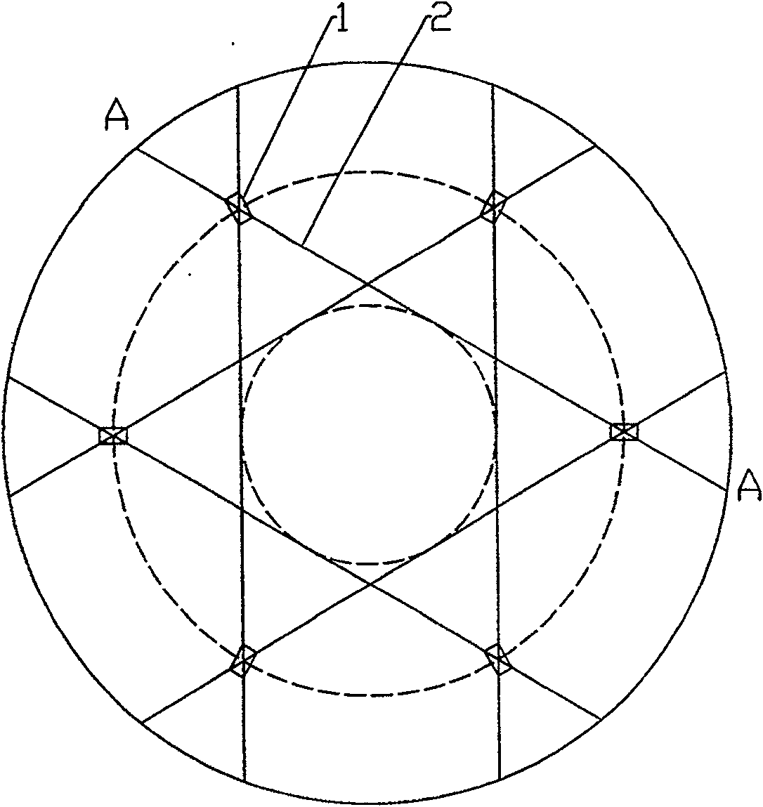
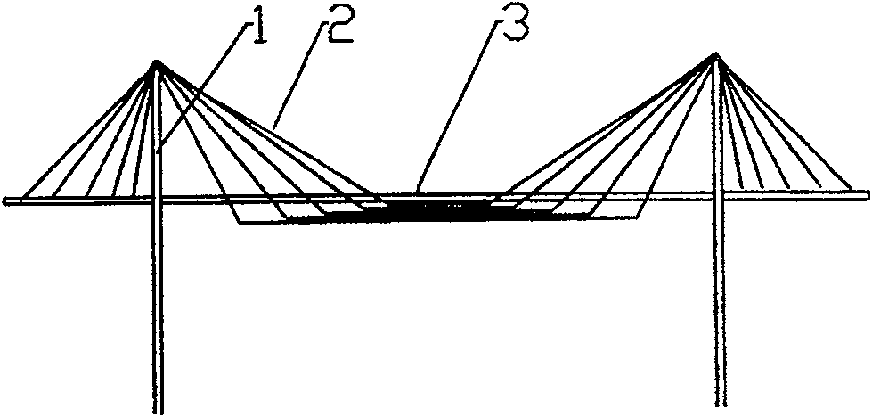
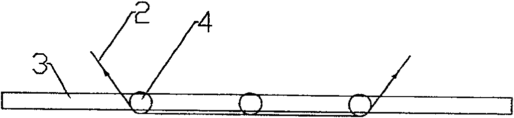
[0024] figure 1 Shown is a schematic diagram of an embodiment of a composite soto roof structure. There are three pairs of main towers 1 in the figure, forming a circular layout, and flexible cables 2 are stretched between each pair of main towers 1 alternately. Cable 2 constitutes a cable net. to combine figure 2 and image 3 As shown, the main girder 4 in the roof structure 3 of the building structure is symmetrically mounted on the flexible cable 2 with the midpoint of the cable 2 as the symmetrical axis, that is, the flexible cable 2 takes the midpoint of the horizontal distance between the two towers 1 as the symmetrical axis from the roof structure. The main girder 4 of 3 passes through, supports the main girder 4, and each flexible cable 2 crosses the cable saddle on the top of the main tower (for the prior art, the cable saddle in the suspension cable structure can be used, omitted in the figure), The two ends are anchored on the anchor head (omitted in the figure)...

Embodiment 2

[0027] like Figure 4 As shown, in this embodiment, 12 main towers 1 form a rectangular layout, and the flexible cables 2 between the main towers form a grid-like cable network to support the main girder of the roof structure from below (omitted in the figure), and the flexible cables Across the cable saddle (omitted in the figure) on the top of the main tower, the two ends of the flexible cable are anchored on the anchor head (omitted in the figure) of the main girder of the roof structure extending out of the main tower 1 .


PUM


Abstract

The invention discloses a kind of compound Soto roof structure, including many to host tower and roof structure, between the main tower long pulls has the flexible rope, the different flexibility sorbs becomes the lattice, flexible rope between two main towers passes through take two towers contour interval central point as the axis of symmetry from the roof structure king post, tows the roof structure in king post, the flexible rope beginnings and ends live by the anchor, this kind of compound Soto roof structure rope efficiency high, main tower highly low, rigidity big, anchorage few, construction convenient, construction cost low, the span is big, especially suits the span is 900~1000m any structure, If large-scale museum; Location; Exhibition hall; Shopping square; Exhibition hall; Thelarge-scale seashore leisure recreation area, the stadium, the hall, the large-scale airplane hangar, the garage, waits for a plane the hall, the waiting room and so on.

Description

technical field [0001] The invention relates to a building structure, in particular to a large-span roof structure. Background technique [0002] In large-span building structures, the roof structure usually adopts a dome structure, and some buildings with larger spans such as hangars usually use a cable-stayed structure and a suspension structure as the roof structure. The structural characteristics of this structure are: through one end directly Fixed (cable-stayed structure) or relatively fixed (suspension cable structure) on multiple pairs of main towers, the other end of the cable or suspension cable is directly pulled on the anchor head on the main beam of the roof structure, that is, the lower end of the cable is fixed on The ends of the main beams of the roof structure. [0003] However, the cable-stayed structure and the suspension cable structure have their own shortcomings due to the characteristics of the structure. The disadvantages of the cable-stayed structur...

Claims


Application Information

Patent Timeline
Patent Type & Authority Patents(China)
IPC IPC(8): E04B7/14E04B1/342
Inventor 徐国彬崔玲
Owner 徐国彬
Why Eureka
Try Eureka