Panel bonding method and panel combination component

A bonding method and technology of composite parts, which are applied in the direction of thin plate connection, connecting member, mechanical equipment, etc., to achieve the effect of strong bonding strength

Inactive Publication Date: 2010-09-15
MURATA MASCH LTD
View PDF5 Cites 0 Cited by
  • Summary
  • Abstract
  • Description
  • Claims
  • Application Information

AI Technical Summary

Problems solved by technology

Therefore, the load concentrates on the engaging portion of the convex portion and the concave portion, and the engaging portion is easily damaged.
In addition, if the position and size of the convex and concave parts are not appropriate, the two plates will shift in position and shake
In addition, in the case of Patent Document 1, when joining two plates, the protrusions provided on one plate are press-fitted into the other plate, recesses are formed on the other plate, and these protrusions and recesses are engaged. Therefore, the position deviation of the two plates is small, but the engagement between the convex part and the concave part is shallow and insufficient, and there is a possibility that sufficient joint strength may not be obtained.

Method used


Image

  • Panel bonding method and panel combination component
  • Panel bonding method and panel combination component
  • Panel bonding method and panel combination component

Examples


Embodiment Construction

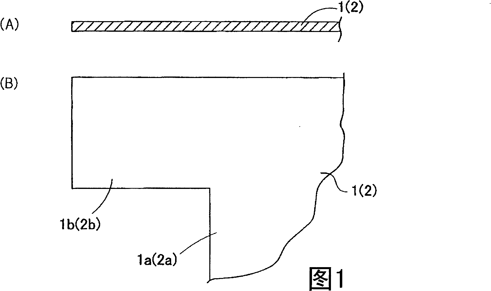
[0034] The plate joining method of the present invention will be described with reference to the accompanying drawings. here, as figure 1 As shown, two metal plates 1, 2 of the same shape in which protruding pieces 1b, 2b as curved pieces are integrally formed with the bases 1a, 2a are joined so that the bases 1a, 2a of the two overlap each other. Example to illustrate. For convenience of description, among the two metal plates, one plate 1 is referred to as a "first plate", and the other plate 2 is referred to as a "second plate".

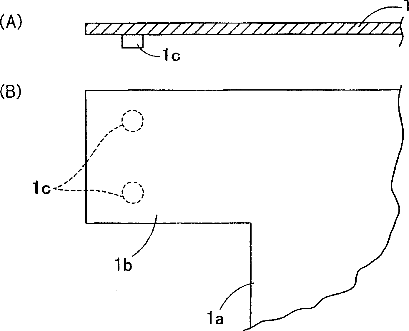
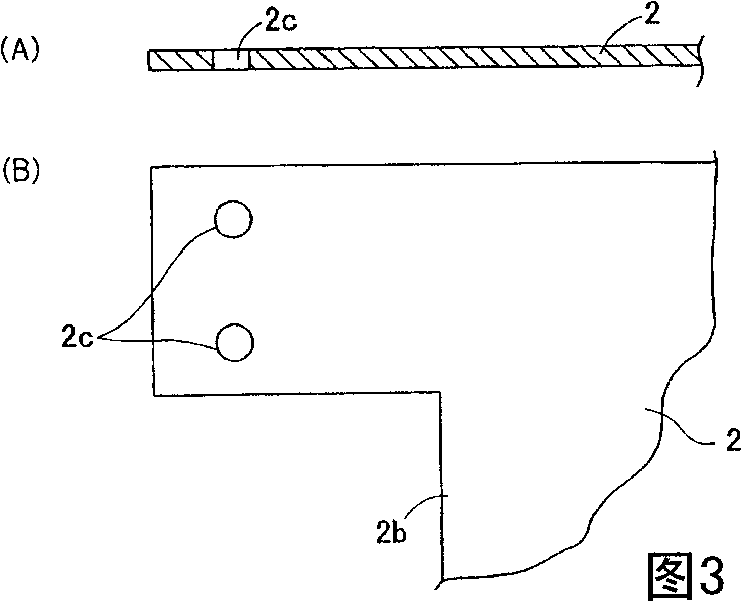
[0035] First, if figure 2 As shown, a dowel 1c is formed in the vicinity of the front end of the protruding piece 1b of the first board 1 . The dowel 1c may be formed by welding, or may be formed by press working. In the illustration, dowels 1c are formed at two positions equidistant from the edge of the protruding piece 1b. In addition, on the protruding piece 2b of the second board 2, such as image 3 As shown, an engaging hole 2c is for...


PUM


Abstract

The aim of the invention is to provide a method for connecting two pieces of sheets, including: a step of forming a bending piece by bending a end part of a first sheet from one of the two sheets made of metal to a sharp angle relatively to a base part of the first sheet; a step of forming a bending piece by bending a end part of a second sheet from the other one of the two sheets made of metal to form an opening of the end relative to a base part of the second sheet, which opening is shorter than a maximum distance between the bending piece and the base part of the first sheet; a step of connecting the first and the second sheets, due to elastic recovery of the bending piece of the first sheet, by inserting the bending piece and the opposite base part of the first sheet into the bending piece and the opposite base part of the second sheet via the opening, and bending the bending piece of the first sheet to a further sharp angle.

Description

technical field [0001] The present invention relates to a sheet joining method for joining two metal sheets without using welding, bolts, etc., and a sheet composite member obtained by joining two metal sheets using the sheet joining method. Background technique [0002] In the process of assembling various articles, machines, structures, etc., two metal plates are generally joined by welding or joining using fastening tools such as bolts. Also, in the assembly of some articles, two metal plates are joined to each other without welding or joining by performing predetermined plastic working on the joint portion of the plates (for example, Patent Document 1). [0003] [Patent Document 1] Japanese Patent Laid-Open No. 7-232227 [0004] In general, joining methods by welding or joining have to weld or join a plurality of locations along the joining portion, so there is a problem of poor work efficiency. [0005] In addition, conventional joining methods that do not use weldin...

Claims


Application Information

Patent Timeline
Patent Type & Authority Patents(China)
IPC IPC(8): B21D39/02B21D5/00F16B5/00
Inventor 松村浩平
Owner MURATA MASCH LTD
Why Eureka
Try Eureka