Investment casted die mould auxiliary moving device

A compression mold and investment casting technology, which is applied in the field of mold auxiliary devices, can solve the problems of inability to adapt to mass production, low productivity, slow speed of push-pull molds and easy sabotage, etc.

Inactive Publication Date: 2007-07-18
CHINA HANGFA GUIZHOU LIYANG AVIATION POWER CO LTD
View PDF0 Cites 4 Cited by
  • Summary
  • Abstract
  • Description
  • Claims
  • Application Information

AI Technical Summary

Problems solved by technology

This method is only suitable for the movement of small and medium-sized molds. For large-scale compression molds with a mold weight greater than 50 kg, pushing and pulling the mold directly on the workbench is labor-intensive and consu

Method used


Image

  • Investment casted die mould auxiliary moving device
  • Investment casted die mould auxiliary moving device
  • Investment casted die mould auxiliary moving device

Examples


Embodiment Construction

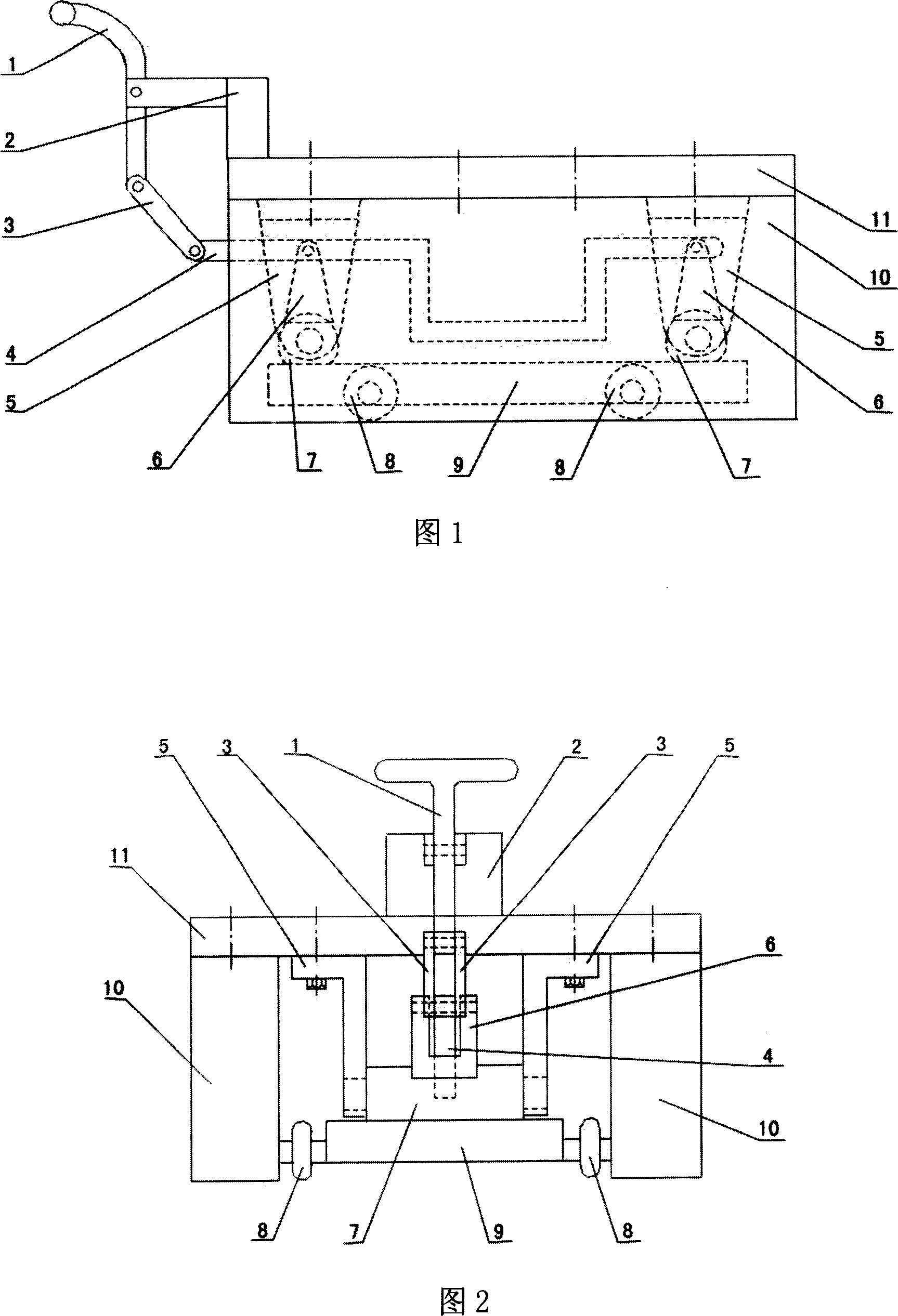
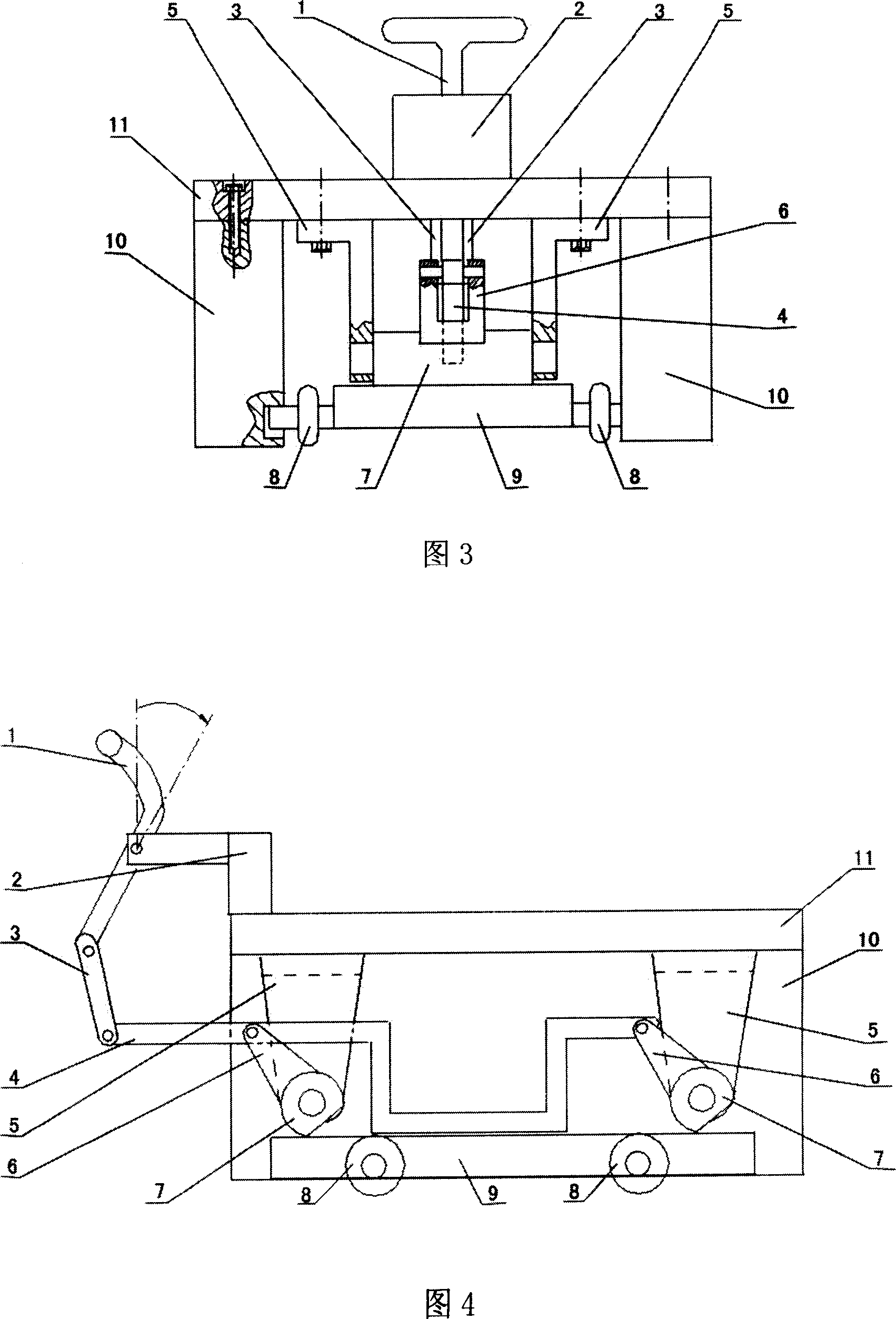
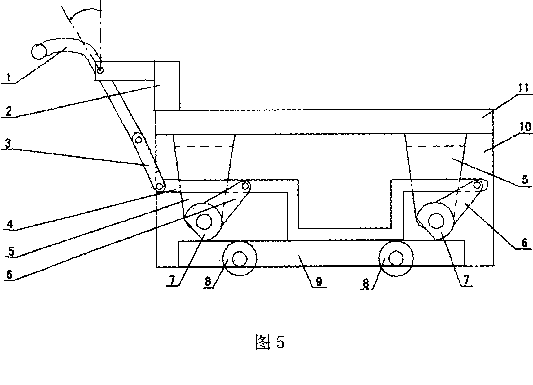
[0018] The auxiliary moving device for the pressure mold of investment casting shown in FIG. 1 is composed of a handle 1 , a flat plate 11 and a roller 8 . On the left side of the upper end surface of the flat plate 11, a supporting platform 2 is welded at the middle position along the width edge, and a round hole is correspondingly opened on the two arms of the supporting platform 2 near the ends. The lower end surface of the flat panel 11 is along the length Both sides of the direction are flush with the edge and are symmetrically installed with two bearing blocks 10 with bolts. Four grooves are correspondingly opened at a distance along the lengthwise direction near the bottom surface on the inner side. Four rollers 8 are symmetrically installed on the four axes of the bottom plate 9 and the four axes are respectively placed in the four grooves of the load-bearing block 10. And can move up and down, the position of groove and the cooperative relation with base plate 9 axles...


PUM


Abstract

The present invention discloses a pattern die auxiliary movement equipment for investment casting process. Said pattern die auxiliary movement equipment is formed from handle, flat-plate and roller. On the flat-plate a supporting table is welded, under said flat-plate a bearing block and a cantilever are mounted, on the shaft of base plate a roller is mounted, and is placed in the groove interior of said bearing block, and can be upwards and downwards moved; on the camshaft a support abutment is wedded, and can be turned in the cantilever interior, the handle, supporting table, link joint, concave connecting rod and support abutment are successively hinge-jointed. Besides, said invention also provides its working principle and concrete operation method.

Description

technical field [0001] The invention relates to an auxiliary device for a mold, in particular to an auxiliary moving device for a die for investment casting. Background technique [0002] The pressure mold of investment casting is mainly used to press the wax model of the casting and the core such as the ceramic core forming the inner cavity of the casting. The structure of the investment casting is generally more complicated, which leads to the complexity of the pressure mold. Before the mold is pressed, it must be assembled by different modules in front of the workbench, and then pushed to the nozzle of the injection machine for injection molding. The mold that has been injected must be pulled out of the injection machine and disassembled to take out the model. The clamping, pushing, pulling out and dismantling of the mold are all done by hand. [0003] Before the present invention appeared, the pushing and pulling out of the profiling mold was carried out directly by pla...

Claims


Application Information

Patent Timeline
IPC IPC(8): B22C19/02
Inventor 彭寿柏刘建平
Owner CHINA HANGFA GUIZHOU LIYANG AVIATION POWER CO LTD
Why Eureka
Try Eureka