Laser pollution removing system and method

A laser and laser beam technology, applied in lasers, laser welding equipment, laser parts and other directions, can solve problems such as environmental pollution, contact wear, dust falling, etc., to avoid environmental pollution and improve the effect of labor-intensive

Inactive Publication Date: 2007-07-18
CHICONY ELECTRONICS
View PDF0 Cites 5 Cited by
  • Summary
  • Abstract
  • Description
  • Claims
  • Application Information

AI Technical Summary

Problems solved by technology

However, the known technology must be manually cleaned, and the solvent used for cleaning will also cause environmental pollution. In addition, when the surface of the contact is ground manually, improper force may cause contact wear, loosening or short circuit, and problems of dust falling

Method used


Image

  • Laser pollution removing system and method
  • Laser pollution removing system and method
  • Laser pollution removing system and method

Examples


Embodiment Construction

[0020] While the invention will be fully described with reference to the accompanying drawings, which contain preferred embodiments of the invention, it should be understood before proceeding that those skilled in the art may modify the invention described herein while still obtaining the benefits of the invention. Therefore, it should be understood that the following description is a broad disclosure for those skilled in the art, and its content is not intended to limit the present invention.

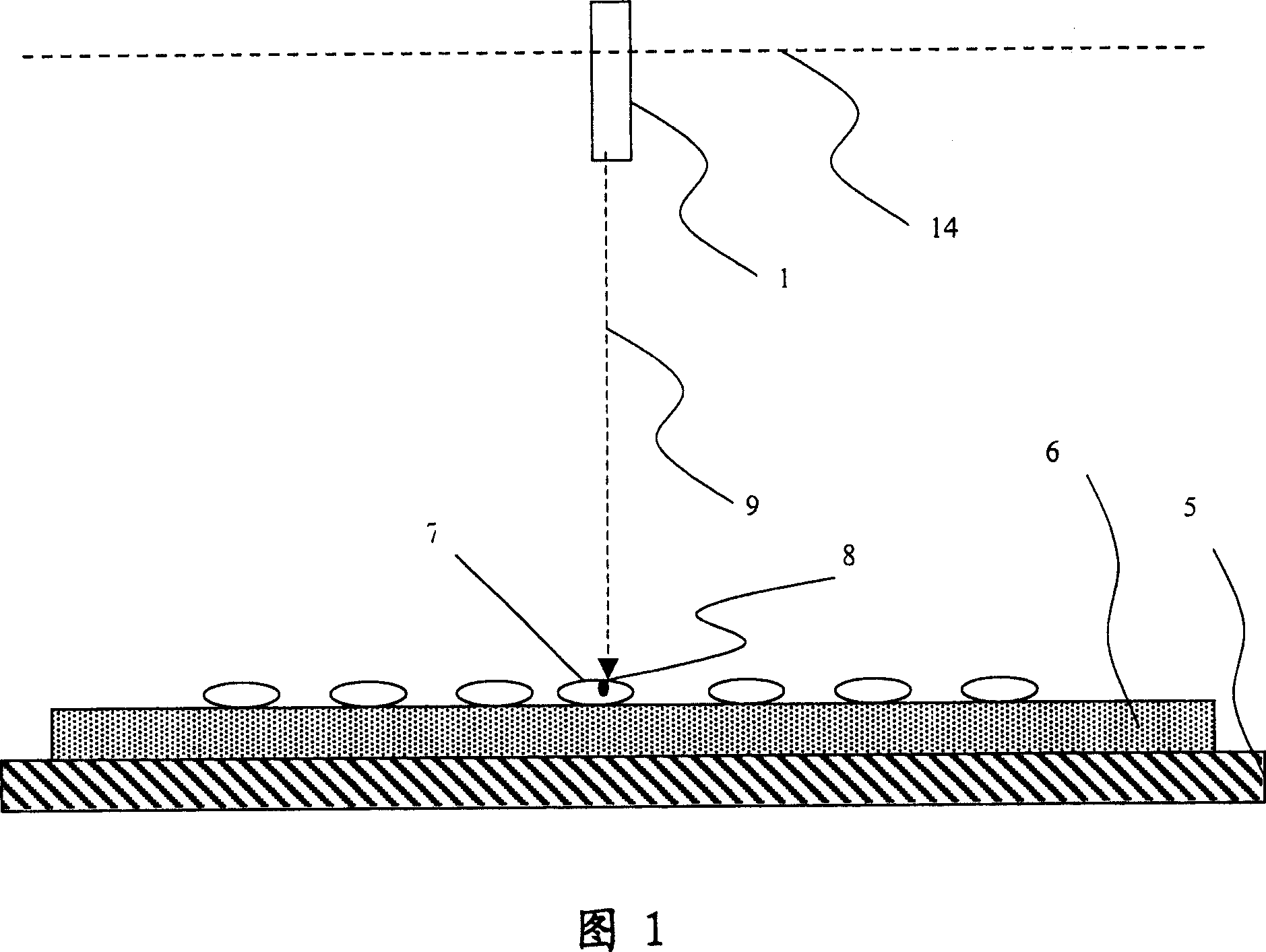
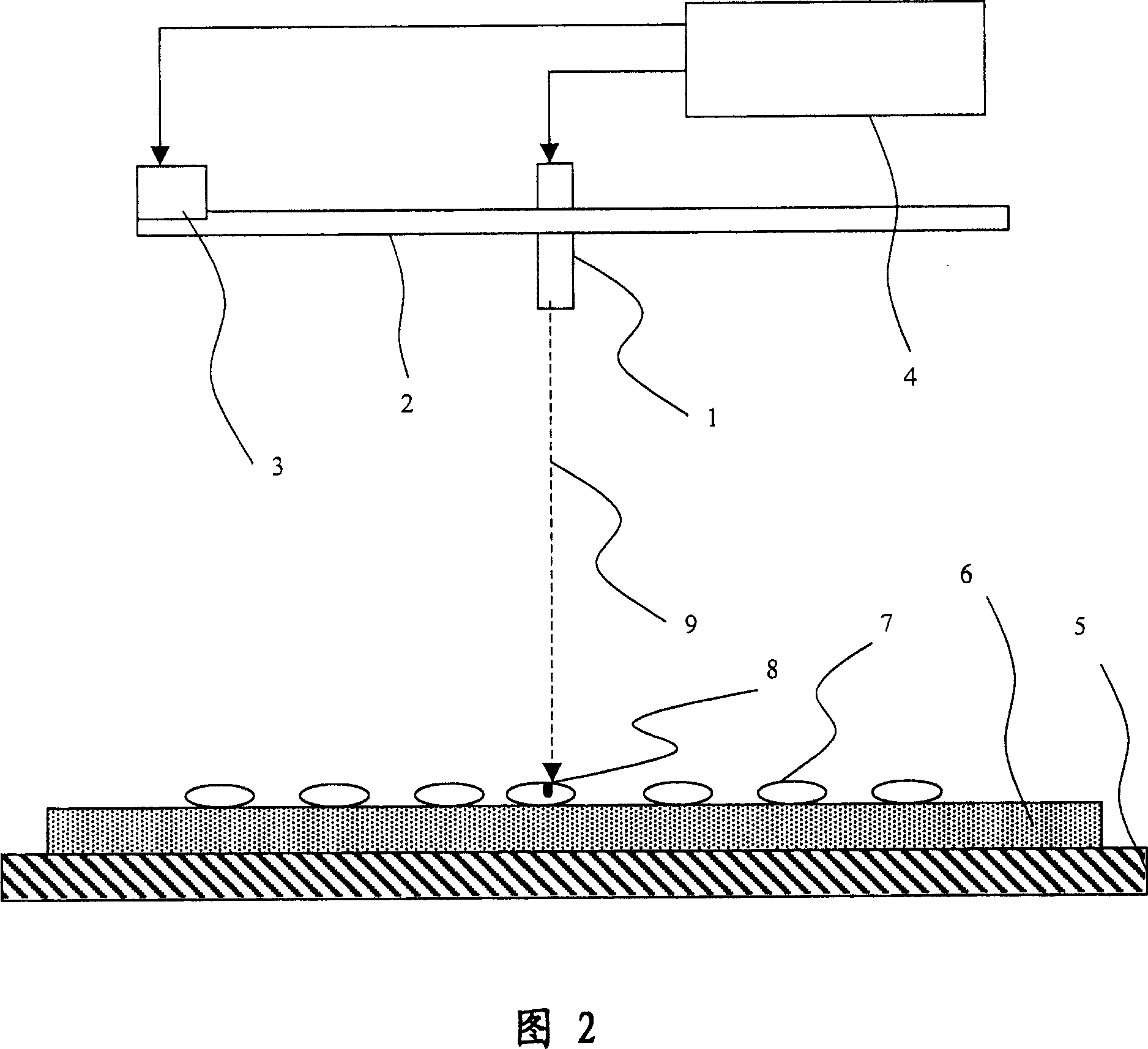
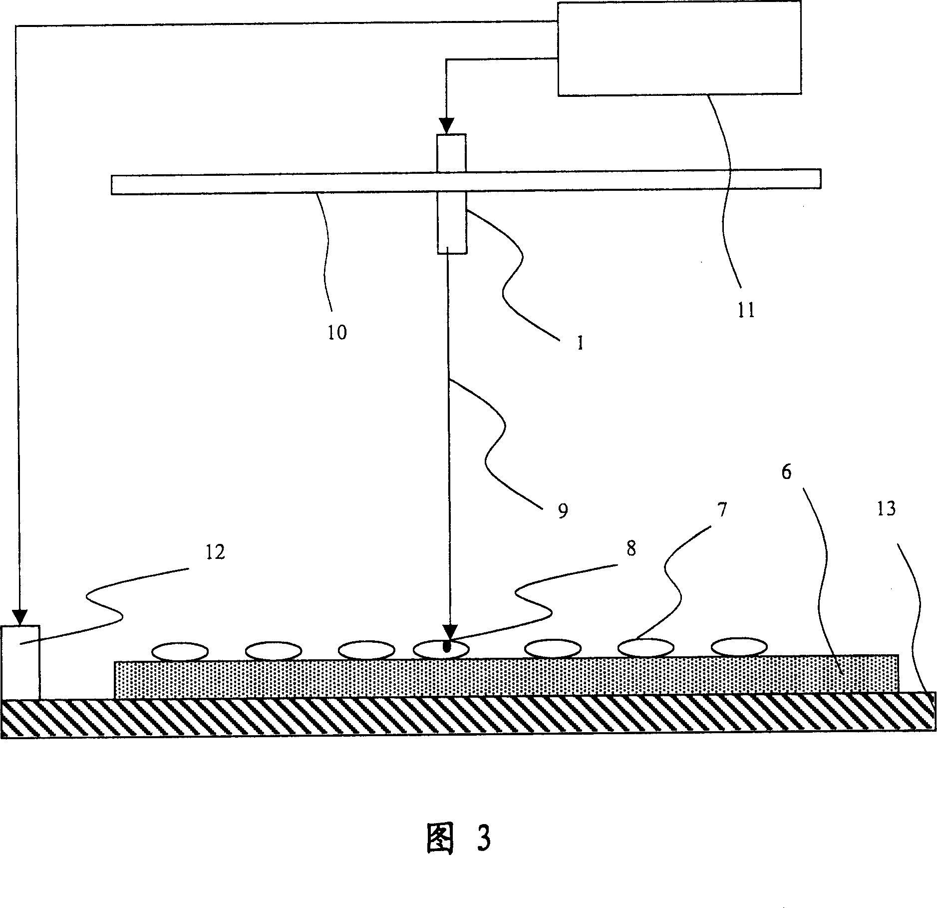
[0021] The operating principle of the present invention can be illustrated by Fig. 1: when decontamination, adjust the relative position of the laser emitting probe 1 and the circuit board 6, so that the contact point 7 is located directly below the laser emitting probe 1, and the laser emitting probe emits a specific The low-power laser of the frequency, the laser hits the stain 8 on the contact 7 along the normal direction 9, and the constituent material of the stain 8 absorbs the ene...


PUM


Abstract

The present invention discloses a laser pollution-removing system and its pollution-removing method. Said method includes the following steps: providing a laser transmission probe which is used for setting the parameters of said laser transmission probe and producing a laser beam; and locating alignment relation ship between laser beam and junction of circuit board. The invented laser pollution-removing system for removing pollutant on the several junctions of a circuit board includes the following several portions: a laser transmission probe for producing a laser beam; a placing platform for fixing a circuit board with several junctions; and a locator for locating alignment relationship between laser beam and junction.

Description

technical field [0001] The invention relates to a decontamination system and method, in particular to a laser decontamination system and method for burning or gasifying pollutants on circuit board contacts by using low-power laser. Background technique [0002] The pollution caused by the contacts on the circuit board mainly comes from the flux, solder oil during soldering, dust and dirt contaminated during the production process, and oxides produced by metal oxidation at the contacts caused by some soldering processes. [0003] Traditionally, to clean the contact pollutants of the circuit board, a special solvent is usually used to wipe and clean the contact surface. If the pollutants still cannot be removed, the friction medium is used to grind the contaminated part of the contact surface. However, the known technology must be manually cleaned, and the solvent used for cleaning will also cause environmental pollution. In addition, when the surface of the contact is ground ...

Claims


Application Information

Patent Timeline
Patent Type & Authority Applications(China)
IPC IPC(8): B23K26/36B23K26/02B23K26/08H01S3/10
Inventor 刘凉荣陈志清
Owner CHICONY ELECTRONICS
Why Eureka
Try Eureka