Deforming adjustable concrete component and preparation method thereof

A concrete structure and concrete technology, applied in the field of concrete components, can solve the problems of poor compatibility of concrete, complex technical means, short service life, etc., and achieve the effects of low cost, simple operation and excellent durability

Inactive Publication Date: 2007-07-18
TONGJI UNIV
View PDF0 Cites 5 Cited by
  • Summary
  • Abstract
  • Description
  • Claims
  • Application Information

AI Technical Summary

Problems solved by technology

The above three methods are not only expensive and complicated in technical means, but also have poor compatibility with concrete, and their service life is short

Method used


Image

  • Deforming adjustable concrete component and preparation method thereof
  • Deforming adjustable concrete component and preparation method thereof
  • Deforming adjustable concrete component and preparation method thereof

Examples


Embodiment 1

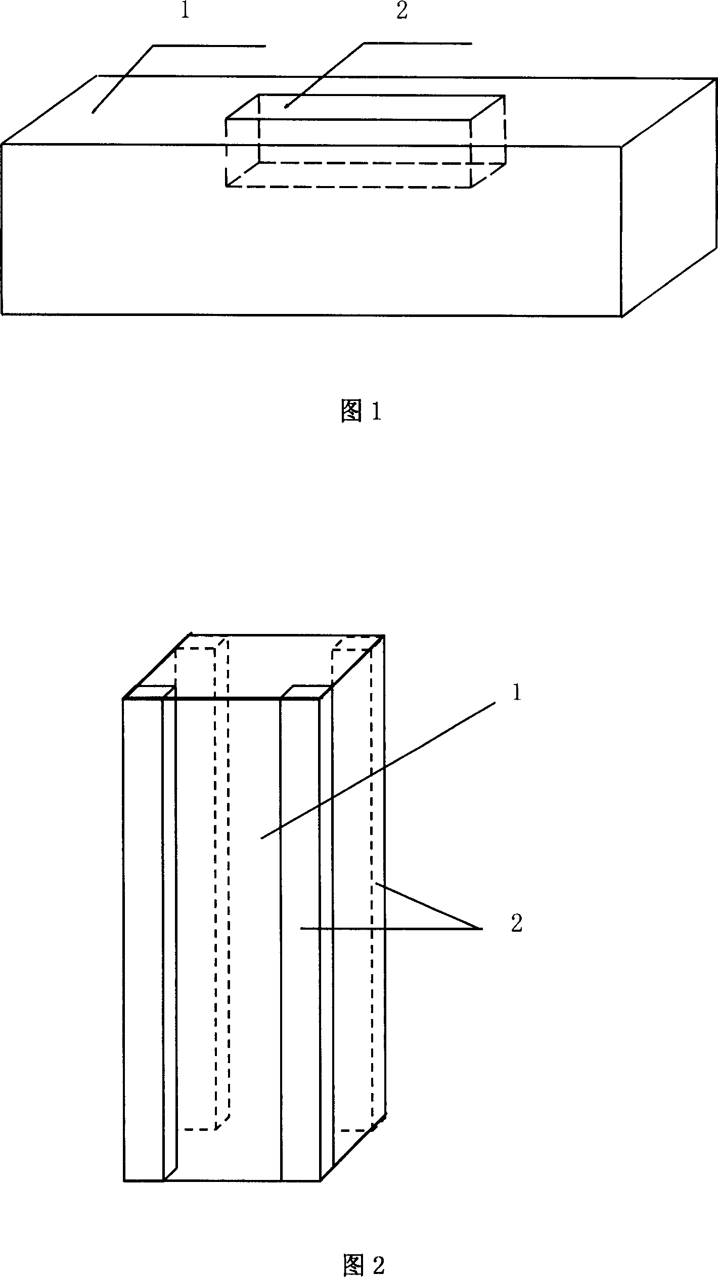
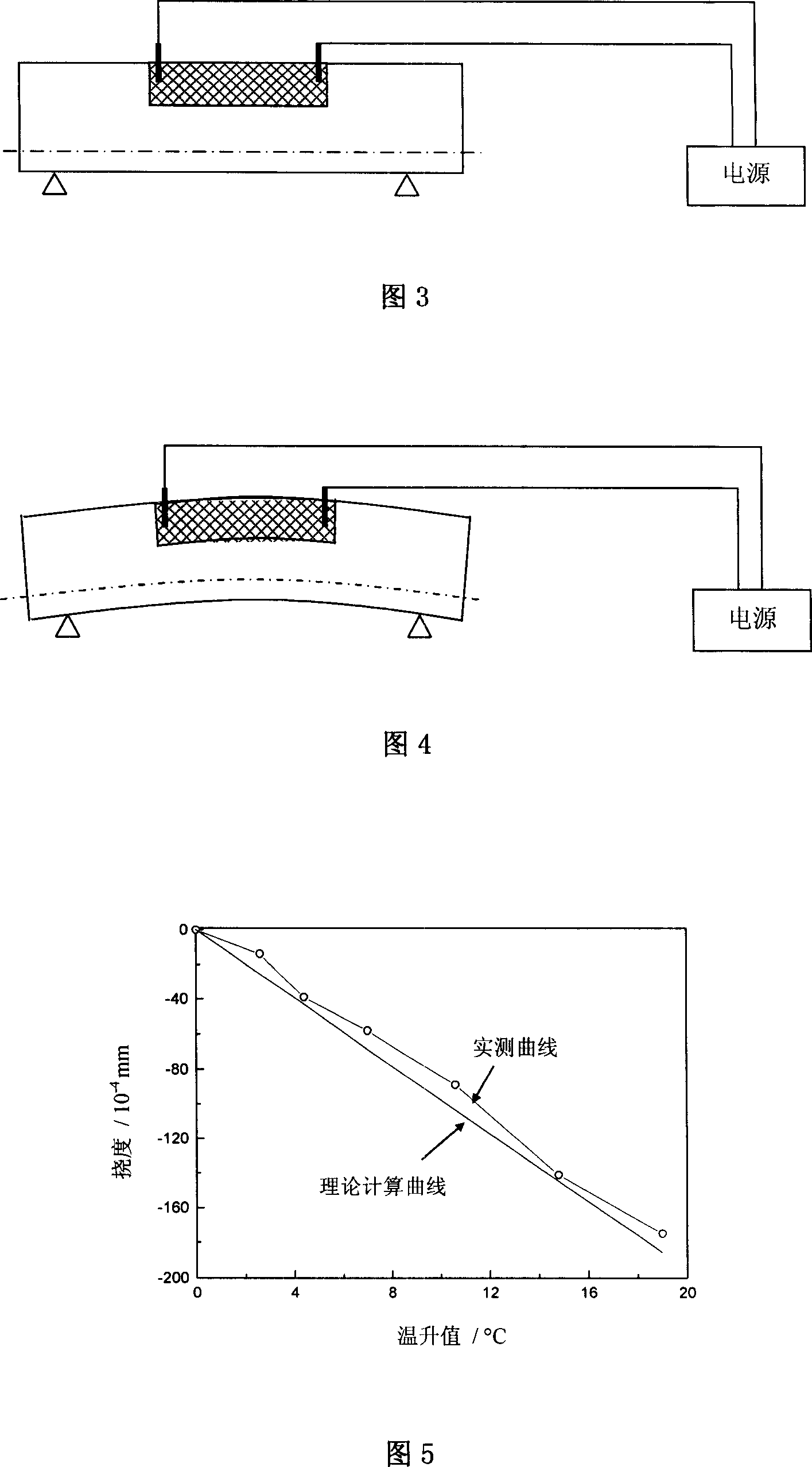
[0026] Example 1: Concrete Beam

[0027] The length, width and height of the concrete beam are: 1200mm×300mm×300mm. The design strength grade of concrete is C35 (35MPa). While pouring the concrete of the beam main body 1, pour carbon fiber reinforced mortar at the mid-span of the beam and above the axis at the same time, and its length, width and height dimensions are: 480mm×120mm×120mm. The upper surface of the carbon fiber reinforced mortar block 2 is located in the same plane as the upper surface of the beam 1 . As shown in Figure 1. Inject the carbon fiber reinforced mortar into the formwork of the corresponding part of the main body, use a vibrator to vibrate for about 2 minutes to remove the internal air bubbles, and then place a stainless steel mesh electrode welded with wires at both ends of the mortar. The stainless steel mesh electrodes are all buried in the mortar. Lead out the mortar. The distance between the two electrodes is 400 mm. The design strength grade...

Embodiment 2

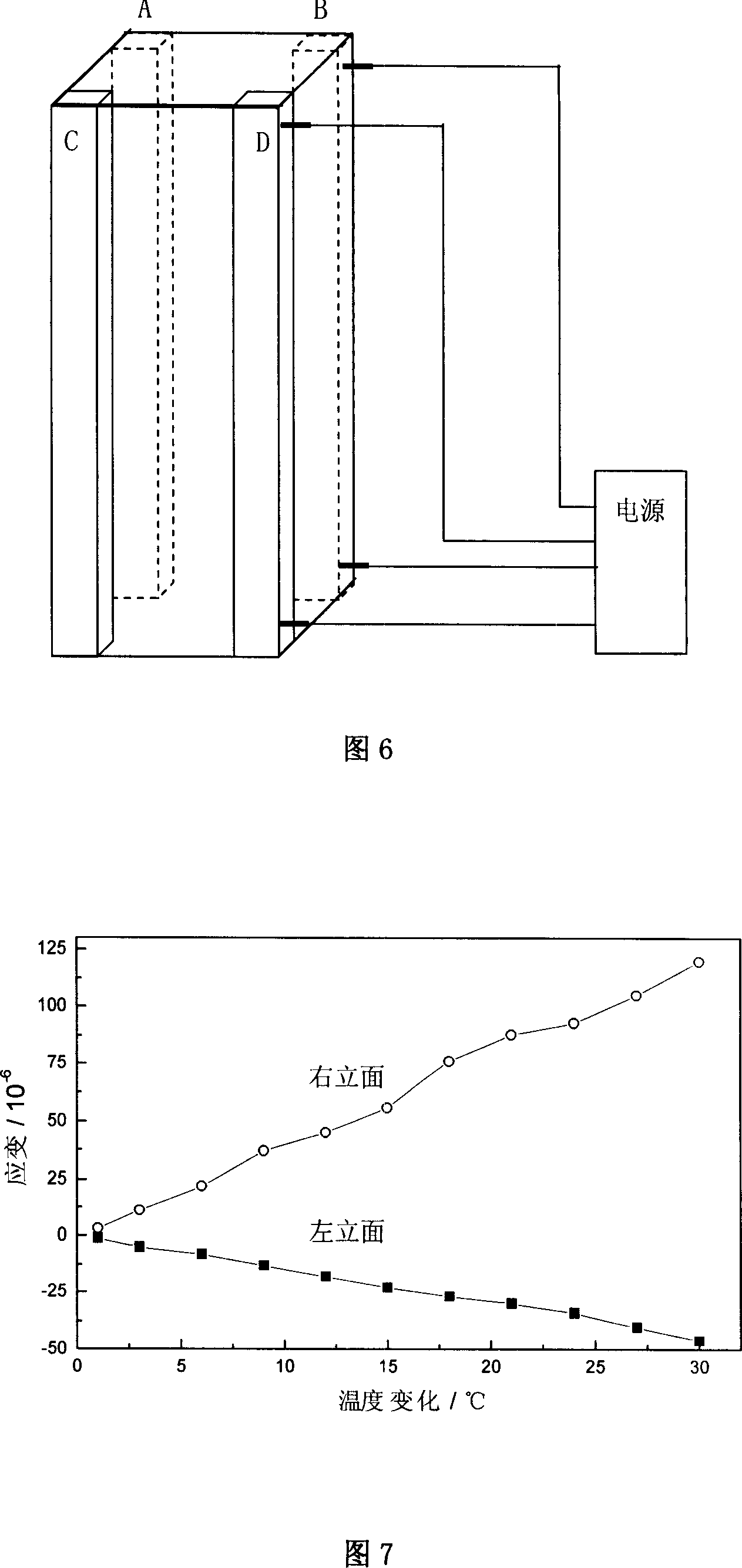
[0042] Example 2: Concrete columns

[0043] The section size of the concrete column is: 400mm×400mm, and the column height is 1200mm. The design strength grade of concrete is C35 (35MPa). Four carbon fiber reinforced mortar prisms are symmetrically poured at the four corners of the column main body 1, the height of which is the same as that of the concrete column, and the cross-sectional size of each prism is 80mm×80mm, as shown in Figure 2. A stainless steel electrode is respectively placed at the upper and lower ends of each carbon fiber reinforced mortar block 2, and is connected with a wire for use. The design strength grade of the mortar is M50 (50MPa).

[0044] The distribution ratio of the components used in the carbon fiber reinforced mortar and the performance after 28 days are the same as in Example 1.

[0045] Place the concrete column vertically, two carbon fiber reinforced mortar prisms A and C are located on the left facade, and the other two carbon fiber rein...


PUM

PropertyMeasurementUnit
electrical resistivityaaaaaaaaaa
lengthaaaaaaaaaa
diameteraaaaaaaaaa

Abstract

The deformation adjustable concrete member includes one main concrete structure body and one carbon fiber reinforced mortar block with electrodes set in the ends embedded inside the main concrete structure body. The carbon fiber reinforced mortar block may be heated electrically to expand, so as to regulate the deformation of the concrete member, eliminate deformation of the concrete member caused by creep strain, fatigue and environment temperature change, maintain or even raise the bearing capacity of the concrete member. The present invention is especially suitable for concrete member with strict requirement in deformation, such as wide span pre-stressed concrete beam, magnetic suspension track beam, etc. the present invention has the advantages of high compatibility, low cost, long service life, simple operation, etc.

Description

technical field [0001] The invention relates to a concrete component, in particular to a concrete component whose deformation can be adjusted. Background technique [0002] Due to the long-term load, fatigue load, temperature difference and other factors, the concrete components will undergo irreversible deformation. The light ones will affect the normal use of the concrete components and need to be repaired and reinforced; the severe ones may cause severe cracking or instability of the components, resulting in disasters. sex accident. At present, important parts of some major infrastructures, such as box girders of long-span bridges and track beams of maglev trains, have strict control indicators for the deformation of components. How to ensure that these important components meet the design requirements during service and how to realize the deformation adjustment of concrete components are hot research topics at home and abroad. At present, the commonly used methods incl...

Claims


Application Information

Patent Timeline
Patent Type & Authority Applications(China)
IPC IPC(8): E04B1/00B28C5/00B28C7/04C04B14/38E04B1/16E04C3/00
Inventor 姚武
Owner TONGJI UNIV
Why Eureka
Try Eureka