
Refraction free curve design method for uniform lighting and its lens

A uniform lighting and design method technology, applied in the direction of lens, optics, instruments, etc., can solve the problems of inapplicability, complexity, and failure to get rid of the excessive volume of the CPC system, and achieve the effect of simple structure, cost reduction, and simplified structure

Inactive Publication Date: 2007-07-18
ZHEJIANG UNIV
View PDF1 Cites 15 Cited by
  • Summary
  • Abstract
  • Description
  • Claims
  • Application Information

AI Technical Summary

Problems solved by technology

Although these methods based on the principle of traditional imaging optics solve the problem of achieving uniform illumination in a specific illumination area, due to their own nature limitations, there is a specific collection angle, so they cannot fully utilize the light energy emitted by LEDs.
At the same time, various solutions require a large number of optical components to cooperate with each other to form an optical system to realize their functions, so they are relatively complicated and not suitable for miniaturized systems. However, miniaturization is increasingly becoming a trend. Today, the limitations of traditional homogeneous lighting systems are becoming more and more obvious
[0004] There are also people who design devices for uniform light based on non-imaging optical principles. For example, John Bortz et al. mentioned in "Advanced nonrotationally symmetrical reflector for efficient and uniform illumination" in 1999 to use an improved CPC system for uniform light, although it is fully Considering the uniformity and light energy utilization rate, but still not able to get rid of the defects that the traditional CPC system is too large, especially the length in the optical axis direction is too long; Mentioned in the use of a free-form surface lens called "mushroom lens (Mushroom Lens)" in conjunction with a corresponding total reflection lens to achieve uniform illumination for a specific area, because its principle determines the total reflection lens used It must be exactly the same size as the area that needs to be illuminated. Although it is very suitable for the design of LCD back power supply, it is not very suitable for other uniform lighting systems

Method used


Image

  • Refraction free curve design method for uniform lighting and its lens
  • Refraction free curve design method for uniform lighting and its lens
  • Refraction free curve design method for uniform lighting and its lens

Examples


Embodiment 1

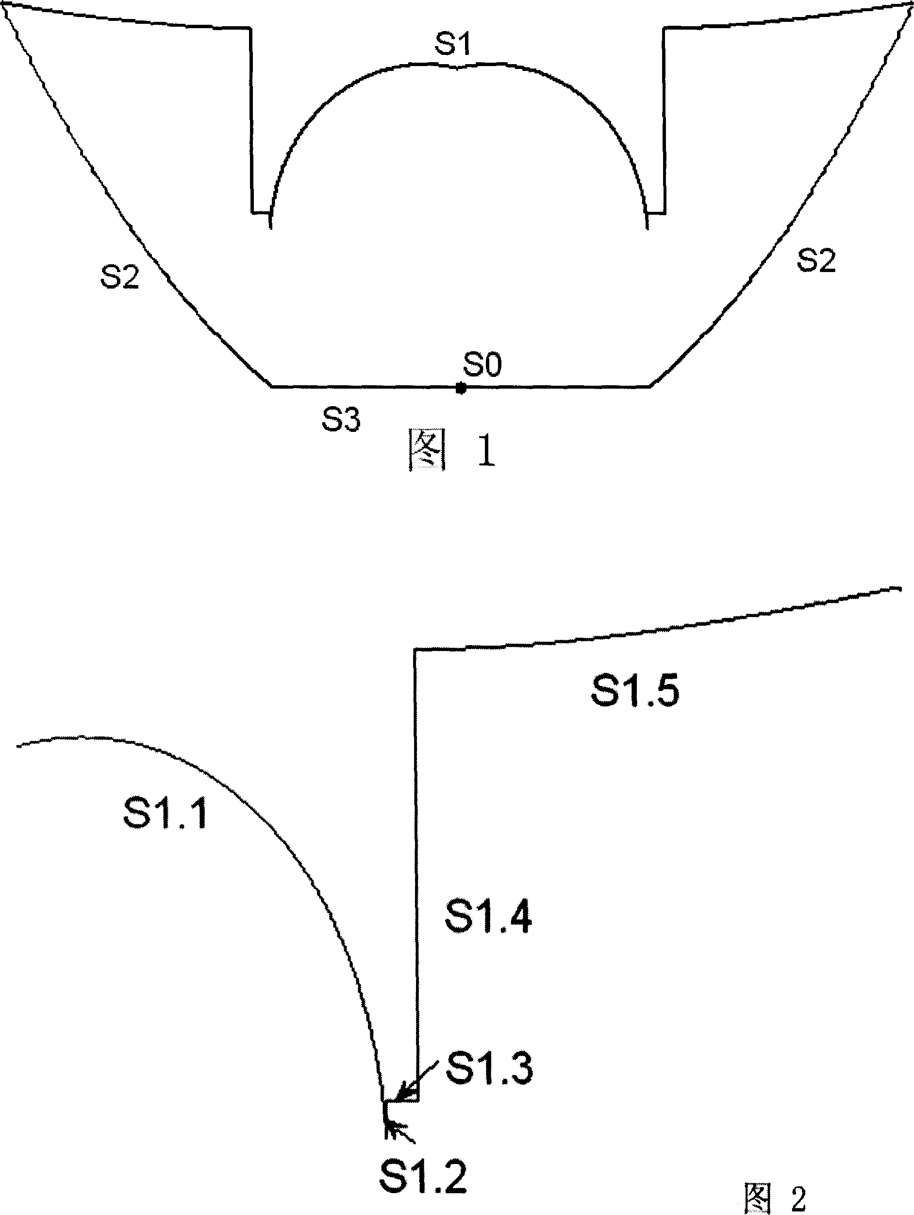
[0097] The following describes in detail the method of realizing the refractive free-form surface lens shown in FIG. 1 by using the above-mentioned mathematical idea. This embodiment is applicable to various light sources with a half light emitting angle of 0°-90°. However, for economical considerations, it is more suitable for light sources with a half-lighting angle of 60°-90° and a large divergence angle.

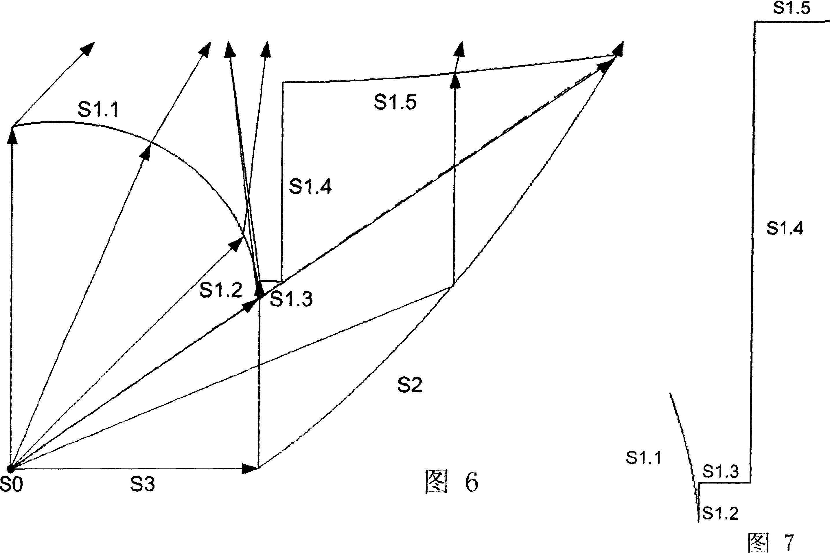
[0098] The refracting free-form surface lens for uniform illumination includes a Lambertian light source S0, a free-form surface S1 for refracting light beams, a reflective surface S2 for reflecting light within a specific divergence angle, and a base surface S3; where S1 includes a central free-form surface S1.1, free-form surfaces S1.3, S1.5, cylindrical surfaces S1.2, S1.4 perpendicular to the base surface S3.

[0099] As shown in FIG. 6 is a schematic diagram of characteristic rays of this embodiment. In order to cover the entire luminous area, the light is artific...

Embodiment 2

[0116] The design method and idea are also applicable to uniform lighting of a specific lighting area with a light source with a small divergence angle of 0-50 degrees, and a simplified structure can be used.

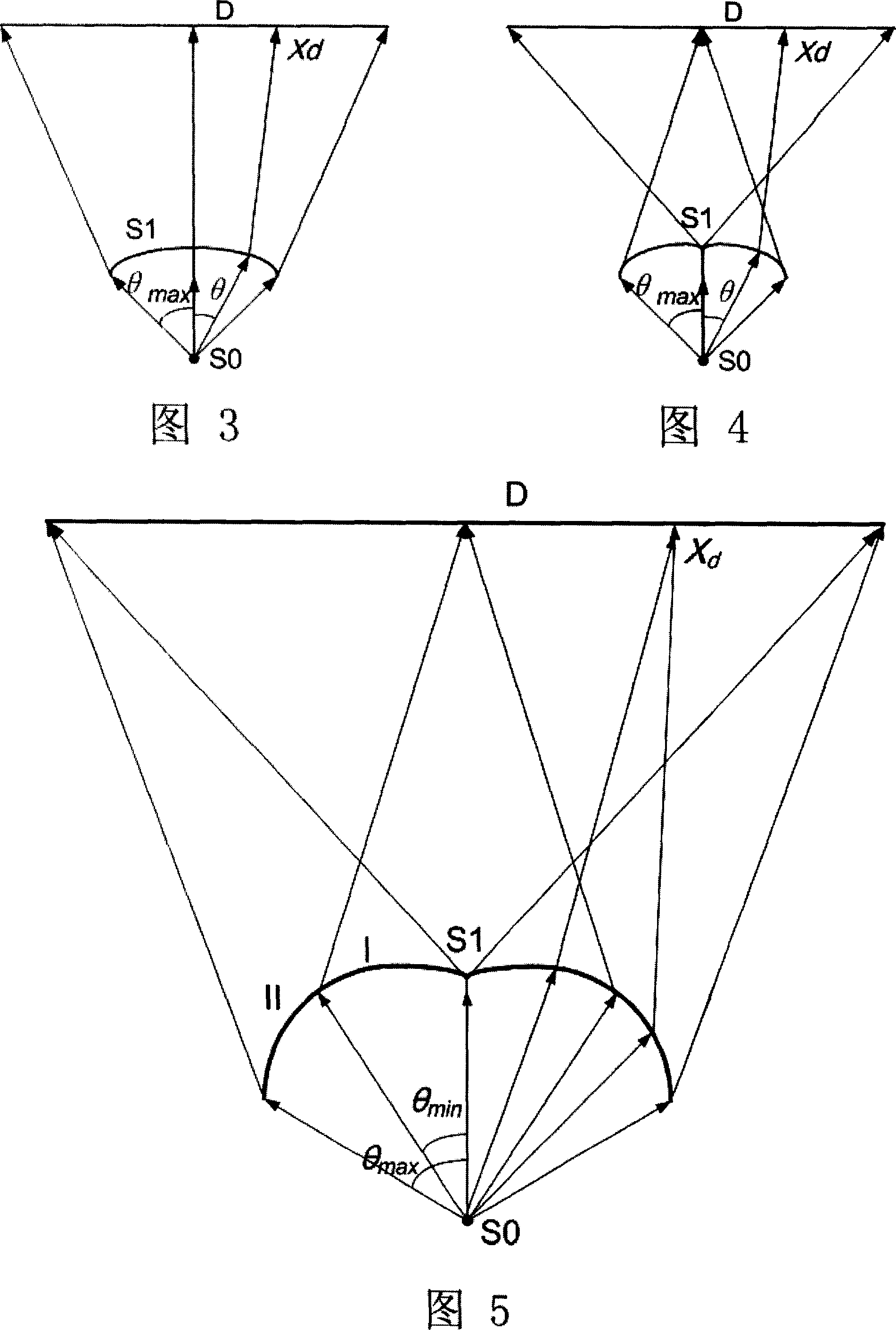
[0117] Fig. 12 shows a schematic diagram of an embodiment of a refractive free-form surface lens applied to a light source with a half light angle φ of 30°. The freeform surface shown in the figure uses the "forward lighting model" shown in Figure 3. In this and the following embodiments, S2 has no reflective function, and is only a cylindrical surface perpendicular to the base surface S3.

[0118] Fig. 13 shows a schematic diagram of another embodiment of a refractive free-form surface lens applied to a light source with a half light emission angle [phi] of 30°. The freeform surface shown in the figure uses the "reverse lighting model" shown in Figure 4.

[0119] FIG. 14 shows a schematic diagram of a third embodiment of a refractive free-form surface lens applied to...

Embodiment 3

[0122] If the refractive index of the medium can be increased from the general 1.5 to more than 1.8, this simplified structure is also applicable to certain larger angles (50-75°). Figure 16 shows the light source applied to a half-light emitting angle  of 60° Schematic diagram of another embodiment of the applied refractive free-form surface lens. The freeform surface shown in the figure uses the "forward lighting model" shown in Figure 3.

[0123] Fig. 17 shows a schematic diagram showing another embodiment of a refractive free-form surface lens applied to a light source with a half light emission angle [phi] of 60°. The freeform surface shown in the figure uses the "mixed lighting model" shown in Figure 5.

[0124] This embodiment applied to a light source with a large divergence angle is mainly applicable to some occasions that have a certain requirement on the total luminous flux (20-40lm) and hope to save energy.


PUM


Abstract

A free curved design used on uniform illumination includes apply Lambert light source, using free curved surface to refract light beam, using side surface to reflect light within specific divergent angle and applying base surface. It is featured as reflecting light in diverging semi-angle being less than 45degree directly to illumination region and refracting light in diverging semi-angle of 45-90degree to illumination region after said light is reflected first.

Description

technical field [0001] The invention belongs to the field of optical technology and lighting technology, and in particular relates to a design method of a refracting free-form surface for uniform lighting and a lens thereof. Background technique [0002] As one of the greatest inventions in human history, artificial light source has had a profound impact on the evolution of human civilization, and it has also continued to improve with the development of science and technology. As a new artificial light source, LED has shown a very broad application prospect due to its small size, low energy consumption, good monochromaticity and other advantages. However, there are still many shortcomings in the current LEDs - the total light energy of a single LED is low, and most LED products have a Lambertian distribution luminescence curve with a large divergence angle (180°), so they are not suitable for lighting alone system. In most applications, people need additional optics to coo...

Claims


Application Information

Patent Timeline
IPC IPC(8): G02B27/00G02B3/00
Inventor 郝翔刘旭丁毅李海峰顾培夫
Owner ZHEJIANG UNIV
Learn More