Liquid crystal display and its driving method and electrode layout method

A liquid crystal display, display electrode technology, applied in static indicators, instruments, nonlinear optics, etc., can solve problems such as the decrease in the penetration rate of the front view angle

Active Publication Date: 2007-07-18
AU OPTRONICS CORP
View PDF0 Cites 11 Cited by
  • Summary
  • Abstract
  • Description
  • Claims
  • Application Information

AI Technical Summary

Problems solved by technology

However, although this capacitive coupling technology achieves the purpose of multi-domain segmentation, it has the disadvantage that the penetration rate at the front view angle also decreases at the same time.

Method used


Image

  • Liquid crystal display and its driving method and electrode layout method
  • Liquid crystal display and its driving method and electrode layout method
  • Liquid crystal display and its driving method and electrode layout method

Examples


Embodiment Construction

[0034] The details of the present invention will be described below through examples with reference to the accompanying drawings. The same symbols or numbers in different drawings indicate the same elements or concepts.

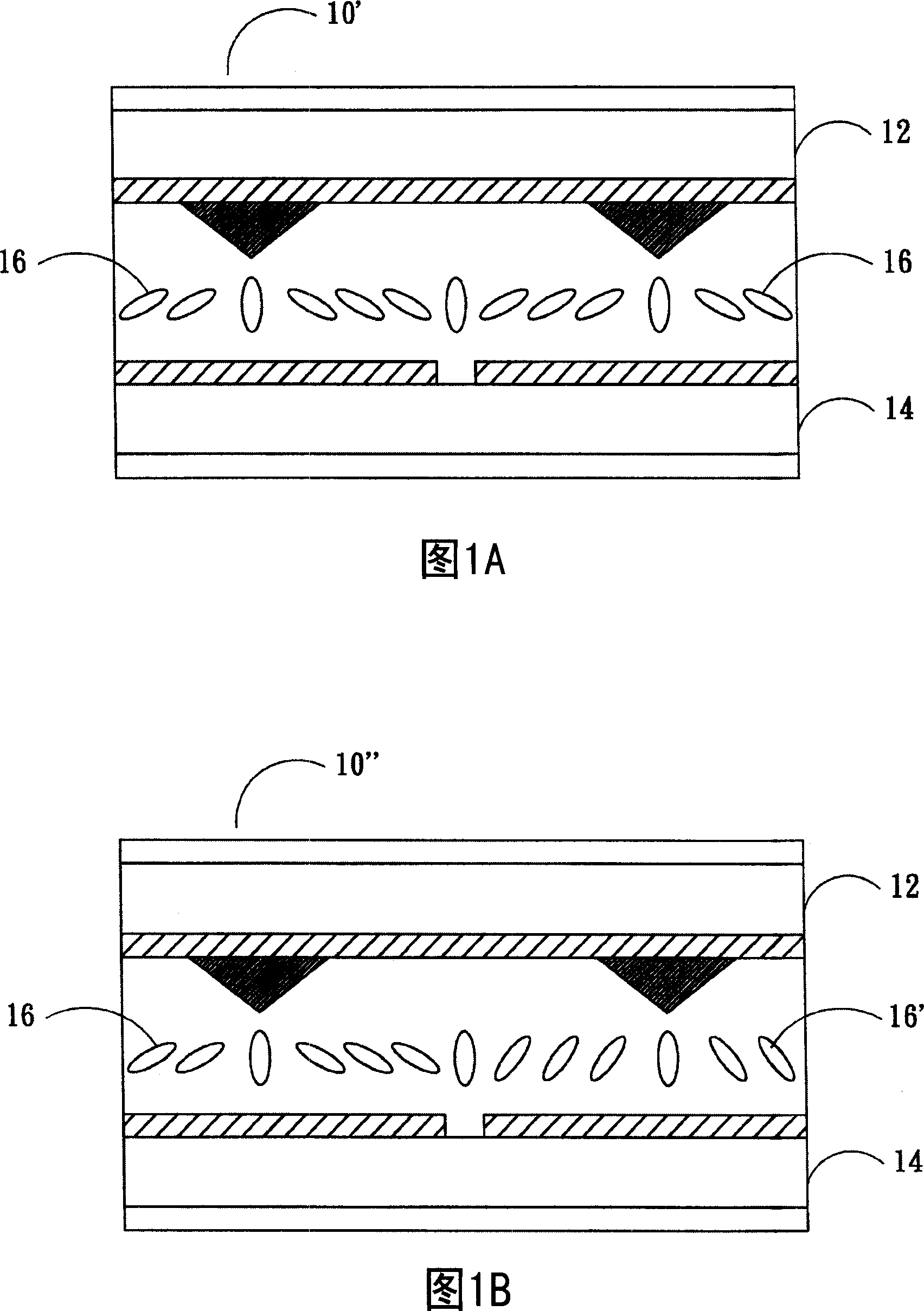
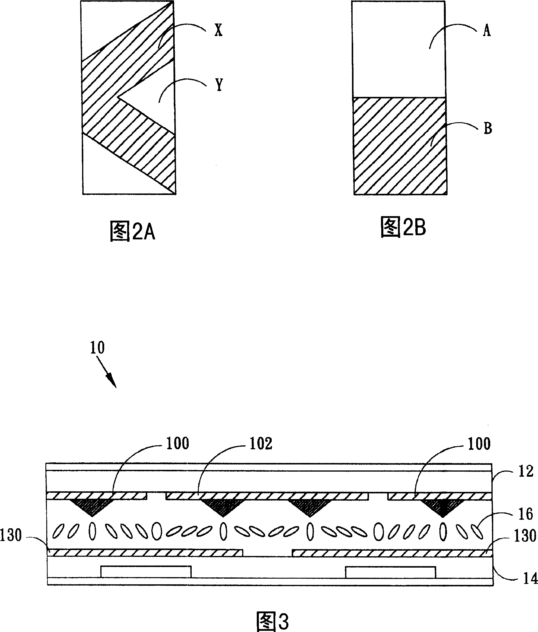
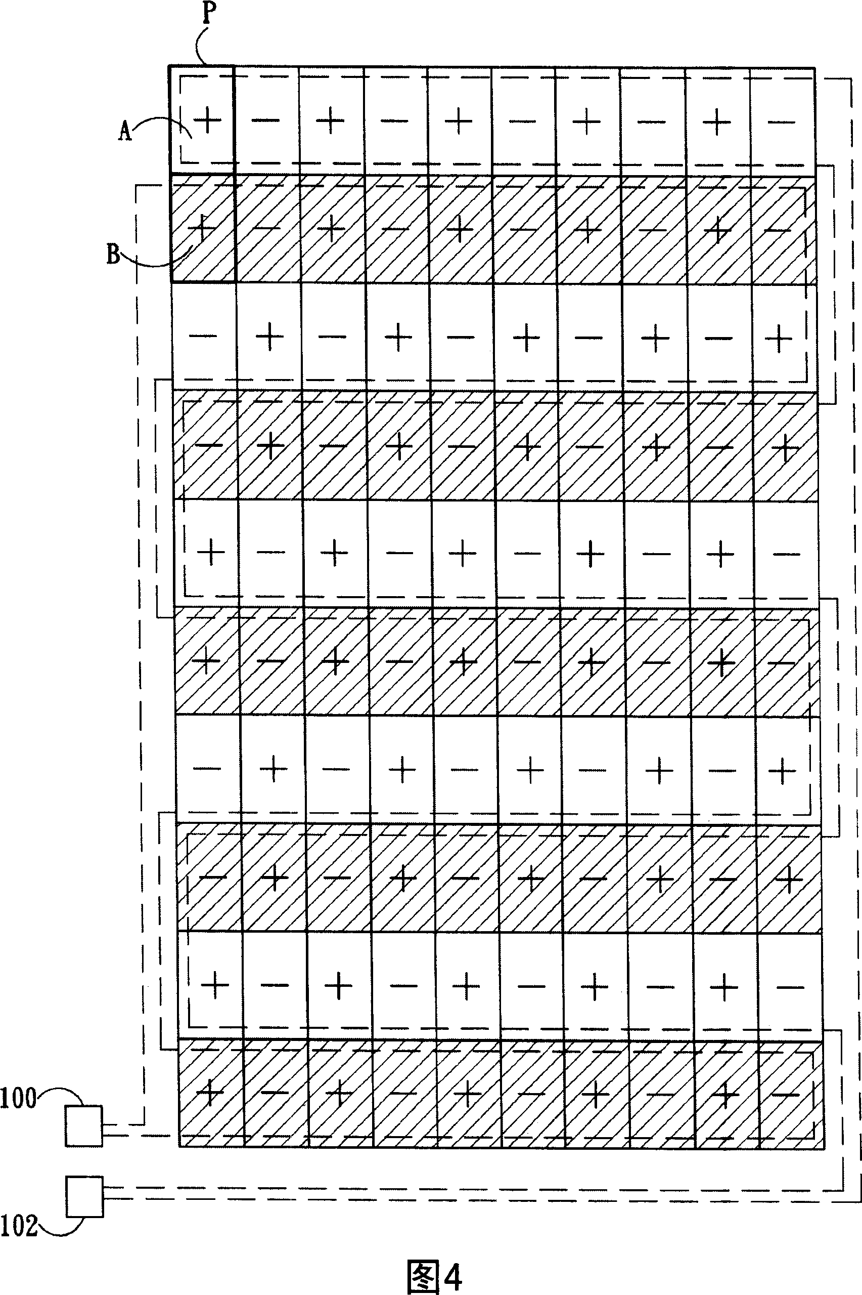
[0035] In order to improve the problem of color distortion in large viewing angles of the liquid crystal display, the present invention divides each unit pixel into two or more sub-pixel regions. Some of the sub-pixel areas have brighter brightness, while other sub-pixel areas have darker brightness, and the combined effect of brightness and darkness will be the same as the original front viewing angle effect, thus improving the situation of wide viewing angles being too bright or too dark, and Applies to every display grayscale. In order to achieve this, it is necessary to make the alignment angles of the liquid crystals in the brighter and darker pixel areas different. The method proposed by an embodiment of the present invention is essentially to divide ...


PUM


Abstract

A liquid crystal display is featured as utilizing reference electrode with two or above different potential distributions to cause variation of liquid crystal arrangement angle in sub-pixel region corresponding to said electrode in order to make Gamma curve and color of display at large visual angle be near to effect of front-view angle and to not influence penetration ratio and display effect of original front-view angle. The driving method and electrode-configuring method of said liquid crystal display are also disclosed.

Description

technical field [0001] The invention relates to a liquid crystal display, in particular to a liquid crystal display with a large viewing angle whose Gamma curve is close to the normal viewing angle and maintains the visual quality of the normal viewing angle, a driving method and an electrode configuration method of the liquid crystal display. Background technique [0002] A liquid crystal display panel usually includes a lower substrate (hereinafter referred to as the first substrate) having unit pixels (pixels) arranged in a matrix and an upper substrate (hereinafter referred to as the second substrate) having a reference electrode (or referred to as the common electrode). Each unit pixel corresponds to a plurality of display electrodes (or called pixel electrodes). That is to say, the visual effect of each unit pixel, such as brightness and color, is a comprehensive result of the potential of all the display electrodes corresponding to it, the potential of the reference e...

Claims


Application Information

Patent Timeline
Patent Type & Authority Applications(China)
IPC IPC(8): G02F1/1343G02F1/133G09G3/36
Inventor 王智伟赖明升黄雪瑛郭峻廷
Owner AU OPTRONICS CORP
Why Eureka
Try Eureka