Transparent display, front light guiding plate and layout method of microstructural pattern of front light guiding plate

A transparent display and transparent display panel technology, which is applied in light guides, optics, instruments, etc., can solve the problems of low transmittance of light guide panels and poor display effects of transparent displays, etc., and achieve good transparency

Inactive Publication Date: 2015-04-22
SHANGHAI XIANGLONG ELECTRONICS TECH
View PDF5 Cites 1 Cited by
  • Summary
  • Abstract
  • Description
  • Claims
  • Application Information

AI Technical Summary

Problems solved by technology

[0004] The technical problem to be solved by the present invention is to provide a method for laying out the transparent display, the front light guide plate and the microstructure pattern of the front light guide plate in order to overcome the defects of the poor display effect of the transparent display and the low penetration rate of the light guide panel

Method used


Image

  • Transparent display, front light guiding plate and layout method of microstructural pattern of front light guiding plate
  • Transparent display, front light guiding plate and layout method of microstructural pattern of front light guiding plate
  • Transparent display, front light guiding plate and layout method of microstructural pattern of front light guiding plate

Examples


Embodiment 1

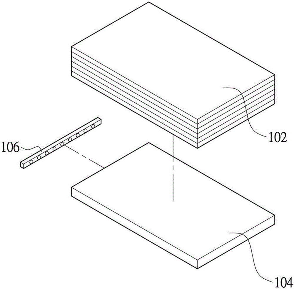
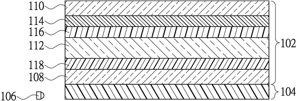
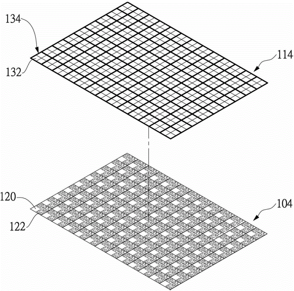
[0062] figure 1 It is a schematic diagram of the decomposition structure of the transparent display in this embodiment, figure 2 is a schematic cross-sectional view of the transparent display of this embodiment, image 3 It is a schematic diagram of the front light guide plate and the color filter layer of the transparent display in this embodiment. Please refer to figure 1 , figure 2 and image 3 , the present embodiment provides a transparent display, which includes a display panel 102, a front light guide plate 104 and a light source 106, the display panel 102 can be a liquid crystal display panel, including a first substrate 108 and a second substrate 110 opposite . A liquid crystal layer 112 is interposed between the first substrate 108 and the second substrate 110, and a first alignment layer 118 is located between the first substrate 108 and the liquid crystal layer 112, and a second alignment layer 116 is located between the second substrate 110 and the liquid c...

Embodiment 2

[0080] The transparent display of this embodiment has many similarities with the transparent display of Embodiment 1, and these similarities will not be repeated. The difference from the transparent display of Embodiment 1 is that, as Figure 6 As shown, the red sub-pixel area 126 , the green sub-pixel area 128 and the blue sub-pixel area 130 of each pixel area are arranged in a straight line and connected to the same side of the transparent area 132 .

[0081] At the same time, if Figure 7 As shown, in this embodiment, the microstructure regions 122 of each corresponding region 124 are arranged in a straight line and connected to the same side of the microstructure-free region 120 .

[0082] In addition, the layout method of the microstructure pattern on the front light guide plate of the transparent display of this embodiment has many similarities with the layout method of Embodiment 1, and these similarities will not be repeated. The difference from the layout method of Em...


PUM


Abstract

The invention discloses a transparent display, a front light guiding plate and a layout method of a microstructural pattern of the front light guiding plate. The transparent display comprises a display panel, the front light guiding plate and a light source, wherein the front light guiding plate comprises a plurality of corresponding areas which respectively correspond to a plurality of pixel areas; each corresponding area comprises microstructural areas of the plurality of sub-pixel areas corresponding to pixel areas and non-microstructural areas of transparent areas corresponding to the pixel areas. The layout method of the microstructural pattern of the front light guiding plate comprises the following steps: S1, generating shield patterns; S2, choosing sample plate patterns; S3, inputting the shield patterns and the sample plate patterns into a machining stand; and S4, pushing the microstructures which are required to be machined in the shield patterns out of the shield patterns through the set machining stand. The transparent display provided by the invention is a transparent display device, and the penetration of the transparent display cannot be influenced because of the microstructures of the front light guiding plate so that the transparent display is high in transparency.

Description

technical field [0001] The present invention relates to a method for arranging a transparent display, a front light guide plate, and a microstructure pattern of a front light guide plate, and in particular to a transparent display, a front light guide plate, and a microstructure pattern of a front light guide plate whose microstructure is designed to avoid a transparent area of ​​a pixel area. Layout method. Background technique [0002] The transparent display panel means that the display panel itself has a certain degree of penetration, and can clearly display the background behind the panel. Transparent display panels are suitable for a variety of applications such as building windows, car windows and shop windows. In addition to the original transparent display function, it also has the potential to be used as an information display in the future, so it has attracted market attention. [0003] Since the transparent display needs to allow the user to see the rear backgr...

Claims


Application Information

Patent Timeline
Patent Type & Authority Applications(China)
IPC IPC(8): G02F1/13357G02B6/00
CPCG02F1/133524G02B6/0058G02F1/133615
Inventor 叶钧皓
Owner SHANGHAI XIANGLONG ELECTRONICS TECH
Why Eureka
Try Eureka