
DC voltage dropping converter

A DC step-down and converter technology, which is applied in the direction of DC power input conversion to DC power output, output power conversion devices, instruments, etc., can solve the problems of insurmountable switching loss, switching loss, reduction, etc.

Inactive Publication Date: 2007-07-18
ASUSTEK COMPUTER INC
View PDF0 Cites 3 Cited by
  • Summary
  • Abstract
  • Description
  • Claims
  • Application Information

AI Technical Summary

Problems solved by technology

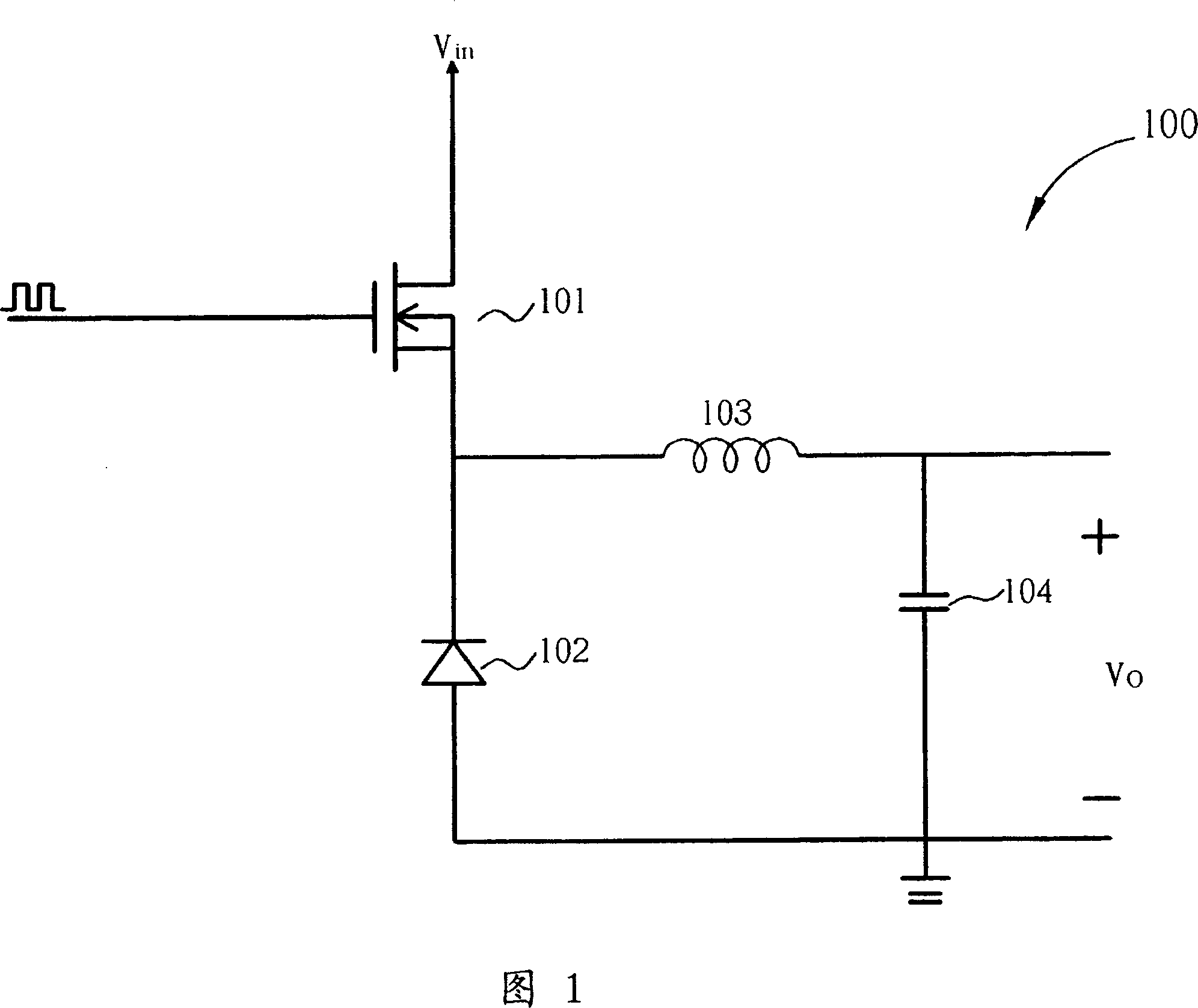
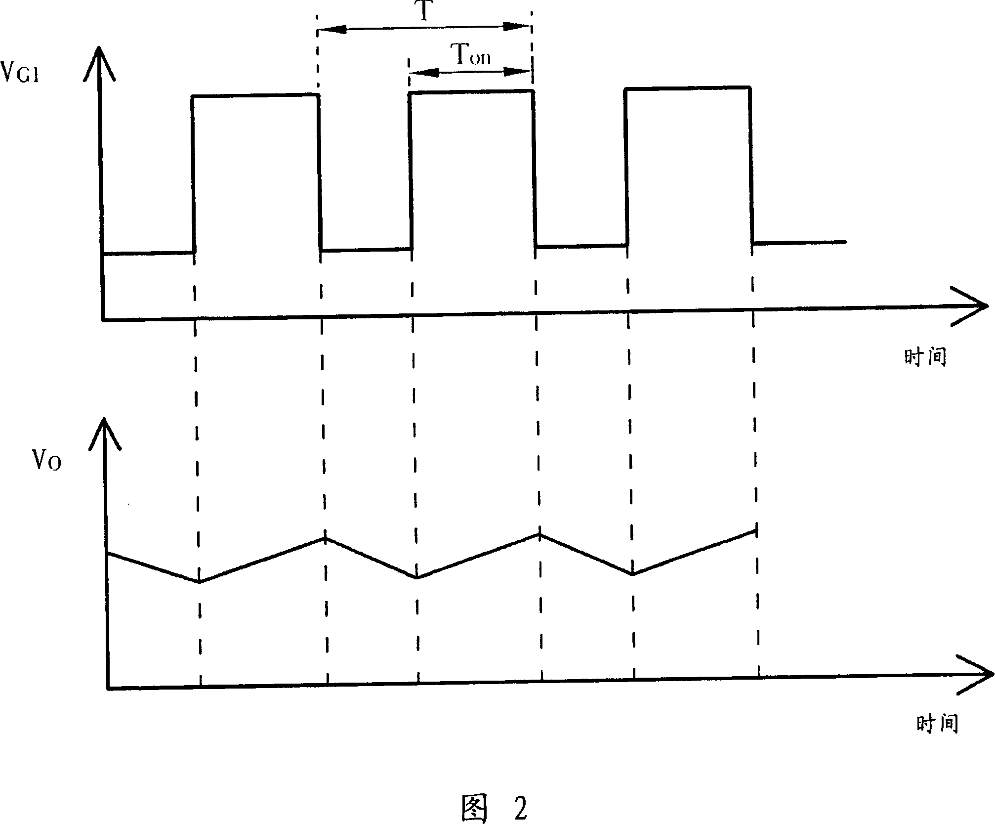
[0006] Please note that the voltage output Vo will fluctuate (ripple), and the magnitude of the fluctuation will affect the quality of the output power of the converter. Therefore, in order to reduce the ripple (ripple), it is generally necessary to increase the control signal V G1 However, when the frequency is higher, the transistor 101 will be continuously turned on and off, resulting in unnecessary switching losses. Furthermore, due to the continuous on and off of the transistor 101, excessive switching losses will be generated. The heat in turn detracts from the service life of the transistor 101
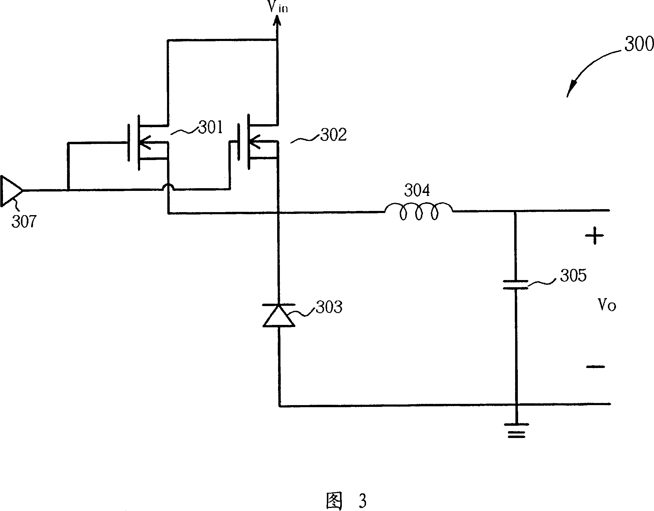
[0007] Please refer to FIG. 3, which is another known circuit diagram of a step-down converter 300. What is different from FIG. The transistor 301 and the transistor 302 can be turned on and off at the same time, thereby reducing the power borne by the transistor 301 and the transistor 302, but here, the transistor 301 and the transistor 302 still cannot overcome the switching loss caused by the high frequency

Method used


Image

  • DC voltage dropping converter
  • DC voltage dropping converter
  • DC voltage dropping converter

Examples


Embodiment Construction

[0023] Please refer to FIG. 4 , which shows a system block diagram of the buck converter 500 of the present invention. The step-down converter 500 includes power input terminals 501, 502, which may be referred to as the first power input terminal and the second power input terminal here, for providing input power, for example, it may be 12 volts or 5 volts, but the step-down of the present invention The power input terminals 501 and 502 of the converter 500 do not limit its application, and it can also be applied to other power supply step-down systems, for example: 9 volts to 5 volts, or 3 volts to 1.8 volts, etc.; control signal source 503, 504, which can be referred to as the first control signal source and the second control signal source here, are used to provide control signals and control the upper arm switch circuits 505 and 506 according to the duty ratio D (Duty ratio) of the control signals; the upper arm switch circuit The first upper arm switch output end and the ...


PUM


Abstract

This invention provides a DC voltage-drop converter including: a first up arm switch circuit having an input end connected to a first supply input end and a control end connected to a first control signal source and the output end, a second up arm switch circuit having an input end connected to a second supply input end and a control end connected to a second control signal source and an output end connected to the first up arm switch output end, a down switch circuit having a first end connected to the output of the first up arm switch circuit and a second end connected to a reference supply and a filter circuit having an input end connected to the output of the first switch and an output end connected to the output of the supply, in which, the first up arm switch circuit and the second will not be conducted at the same time.

Description

technical field [0001] The invention relates to a step-down converter, in particular to a direct-current step-down converter. Background technique [0002] In electronic products, usually only a few main power supplies are provided, for example, 12 volts (Volt), 9 volts, but there are various integrated circuits (Integrated Circuit) with different functions in the system, and these integrated circuits use different power supplies respectively , such as 5 volt power supply, 3.3 volt power supply, then a set of converters are needed to convert the voltage. [0003] Please refer to FIG. 1 , which is a circuit diagram of a known buck converter 100 . A power supply V in It is supplied to the input terminal of the transistor 101; the transistor 101 has a control terminal and an output terminal, and the output terminal is electrically connected to the first terminal of the diode 102; the second terminal of the diode 102 is grounded; the first terminal of the inductor 103 is elect...

Claims


Application Information

Patent Timeline
IPC IPC(8): H02M3/10H02M3/155
Inventor 洪祥睿陈熯勋林存森杨孙成
Owner ASUSTEK COMPUTER INC
Learn More