
Blind person way guiding device with electronic marks

A technology of electronic signs and guidance devices, applied to roads, roads, road lights, etc., can solve the problems of inability to realize the guidance function, and achieve the effect of convenient use

Inactive Publication Date: 2007-07-25
丁文礼
View PDF0 Cites 4 Cited by
  • Summary
  • Abstract
  • Description
  • Claims
  • Application Information

AI Technical Summary

Problems solved by technology

The current tactile path only provides walking for the blind, and cannot realize the guiding function

Method used


Image

  • Blind person way guiding device with electronic marks

Examples


Embodiment Construction

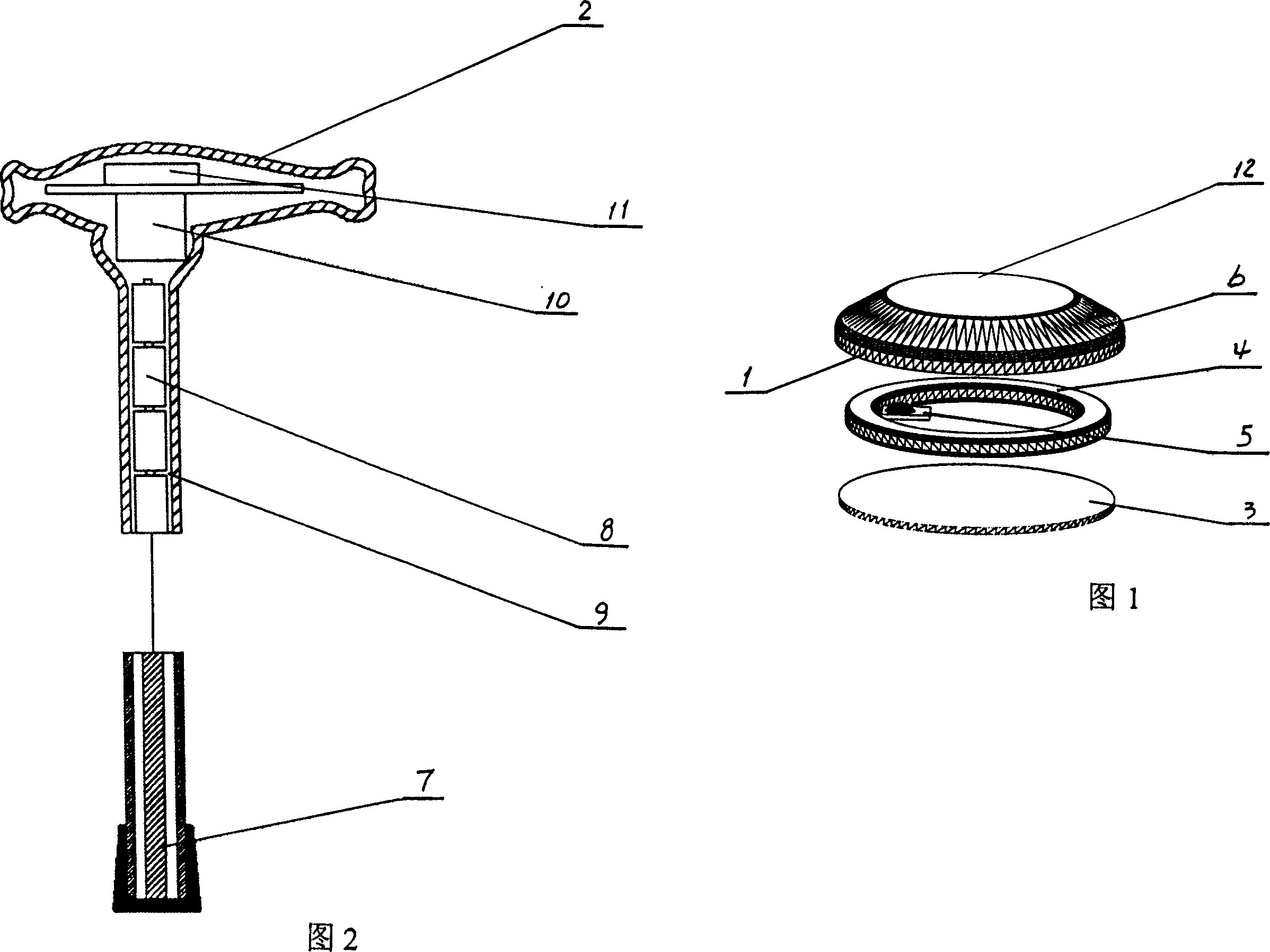
[0009] Referring to Fig. 1, among the present invention, electronic identification nail 1 is made up of base plate 3, induction coil 4, information module 5 and shell 6, and induction coil 4, information module 5 are fixed on the base plate 3, and shell 6 is fastened with base plate 3; Information module 5 records road signs and road condition information. The electronic identification nails 1 are arranged at intervals and continuously in the blind road. The raised part 12 on the top of the shell 6 is consistent with the road surface of the blind road. The electronic identification nails 1 are located at intersections, forks and places with special road signs Both need to be set.

[0010] Referring to FIG. 2 , in the present invention, the head of the sensing blind stick 2 is provided with a sensor 7 , a reading module 8 and a charging interface 9 are provided in the rod, and an output module 10 and a signal processing module 11 are provided in the handle. When a blind person ...


PUM


Abstract

A guiding facility for blind people way is composed of an inductive blind stick and electronic marker nails arranged in blind people way at intervals. Said electronic marker nail consists of base plate, induction coil, information module and shell. Said blind stick comprises an inductor at its front end, the read-out module and recharge interface in its stick rod, and the output module and signal processing module in its handle for converting the induced signal to sound or vibration.

Description

technical field [0001] The invention relates to blind road guidance technology, in particular to a device for guiding blind people to walk by using electronic signs on blind roads. Background technique [0002] The existing tactile walkways are mostly made of special textured floor tiles or pasted on the ground with special textured paving layers. The blind walkway is set on the sidewalk and will be interrupted at intersections or in front of government agencies. When blind people continue to walk or change When walking in the direction, they often need help from others, especially after a blind person walks for a certain distance, they need to ask others to know where they are. Existing blind roads only provide walking for the blind, and cannot realize the guiding function. Contents of the invention [0003] The purpose of the present invention is to provide a blind road guide device with electronic signs for the deficiencies of the prior art, which can inform blind peop...

Claims


Application Information

Patent Timeline
Patent Type & Authority Applications(China)
IPC IPC(8): A61F9/08E01C17/00
Inventor 丁文礼
Owner 丁文礼
Learn More