Double suction microminiature type vane pump with no spindle drive

An ultra-small vane pump technology, which is applied to the components, pumps, and pump devices of pumping devices for elastic fluids. It can solve the problems of reduced hydraulic efficiency and difficulty in optimizing and controlling the flow of ultra-small vane pumps. Axial load, elimination of stagnation zone, reduction of the effect of axial water thrust

Inactive Publication Date: 2007-07-25
TSINGHUA UNIV
View PDF0 Cites 14 Cited by
  • Summary
  • Abstract
  • Description
  • Claims
  • Application Information

AI Technical Summary

Problems solved by technology

However, after the flushing hole is added, the flow of the ultra-small vane pump is difficult to optimize and control, and the hydraulic efficiency is reduced

Method used


Image

  • Double suction microminiature type vane pump with no spindle drive

Examples


Embodiment Construction

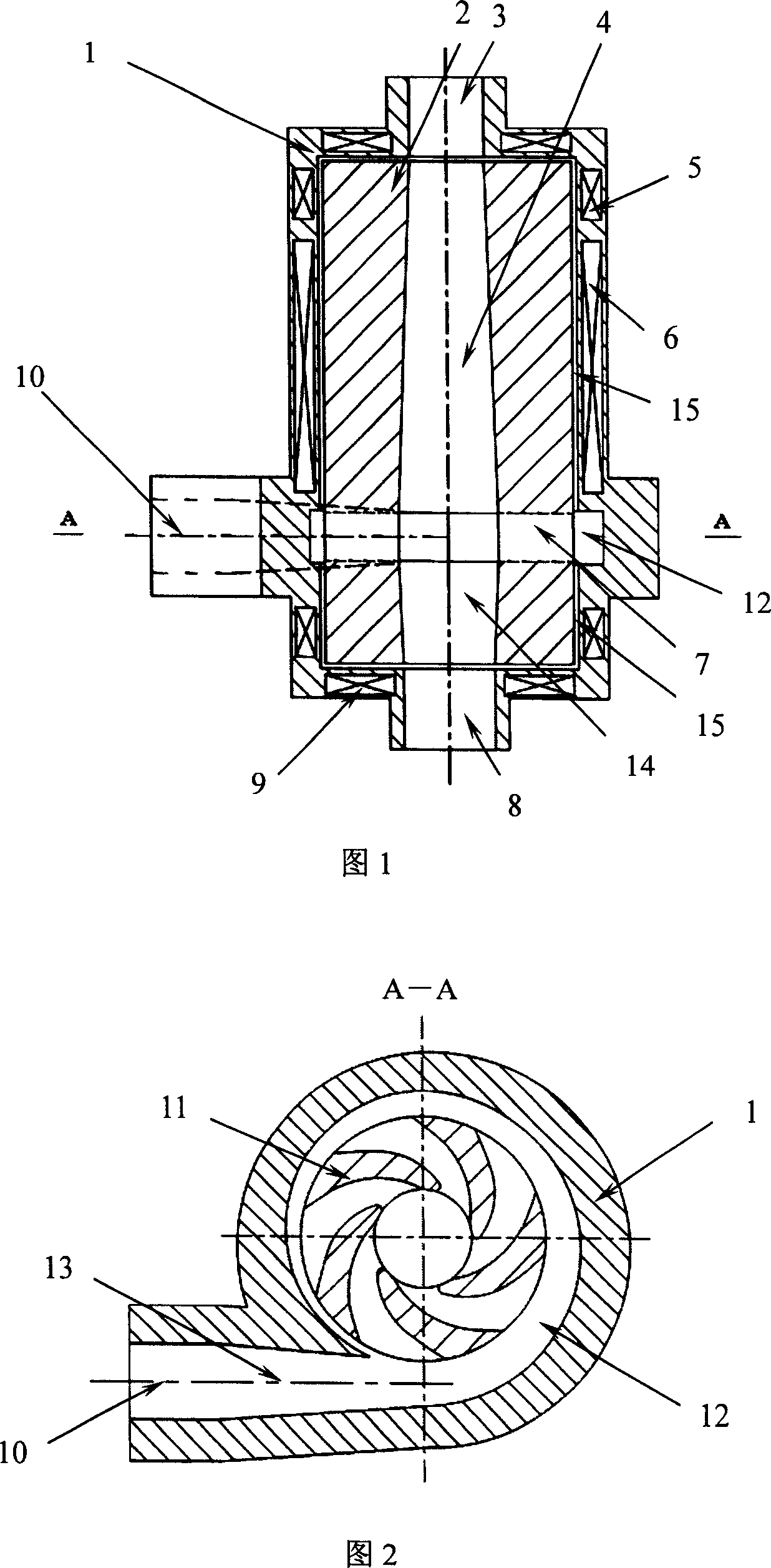
[0014] Principle of the present invention, structure are further described below in conjunction with accompanying drawing

[0015] Figure 1 is a main sectional view of a double-suction shaftless driven ultra-small vane pump. The ultra-small vane pump includes a pump body 1 , a pump first suction port 3 , a pump second suction port 8 , a pump impeller 7 , a motor rotor 2 , a motor stator 6 , a pressurized water chamber 12 and a pump outlet 10 .

[0016] The pump impeller 7 is integrated with the motor rotor 2, and the center of the motor rotor 2 is provided with a first impeller inlet 4 and a second impeller inlet 14, which communicate with the first pump suction port 3 and the second pump suction port 8 respectively. A pressurized water chamber 12 is provided on the outer periphery of the pump impeller, and a diffusion section 13 is provided between the pump outlet 10 and the pressurized water chamber 12 . Wherein the first suction port 3 of the pump, the second suction port ...


PUM


Abstract

The present invention relates to a double-suction microminiature paddle pump. It is characterized by that its pump paddle wheel and motor rotor are formed into one body, the centre of said motor rotor is equipped with two paddle wheel inlets which are respectively communicated with pump paddle wheel, the cross-sectional area of said two inlets is progressively expanded along flowing direction; said two paddle wheel inlets ar respectively communicated with two suction inlets of pump. Said pump has no need of mechanical drive shaft, and can implement high-effective and safety conveyance.

Description

technical field [0001] The invention relates to a small vane pump, in particular to an ultra-small vane pump suitable for no circumscribed shaft, no fluid leakage or contact with the outside of the pump. The invention can be applied to delivery devices for single-phase or multi-phase fluids such as extracorporeal blood circulation devices, artificial hearts, chemical agents and liquid precious metals. Background technique [0002] Due to the advantages of ultra-small vane pumps in space size, they have been applied in many important industries. The ultra-small vane pumps currently used are mainly divided into two categories according to the structure of the shaft: one is in the form of an external shaft, and the other is in the form of magnetic levitation. For ultra-small vane pumps with external shafts, due to the use of mechanical seals or other shaft sealing devices, the fluid in the pump cannot be completely isolated from the outside of the pump, and cannot effectively ...

Claims


Application Information

Patent Timeline
Patent Type & Authority Applications(China)
IPC IPC(8): F04D13/06F04D29/24F04D29/44F04D29/048H02K7/09
Inventor 罗先武刘树红许洪元张瑶李莹
Owner TSINGHUA UNIV
Why Eureka
Try Eureka