Hydraulic design method for efficient and large-flow vortex pump quasi-annulus pumping chamber

A technology of annular pressurized water chamber and hydraulic design, which is applied to parts, pumps, and pump components of pumping devices used for elastic fluids, and can solve problems that do not involve the improvement of the structure and structural form of swirl pump pressurized water chambers

Active Publication Date: 2015-11-11
JIANGSU UNIV
View PDF10 Cites 8 Cited by
  • Summary
  • Abstract
  • Description
  • Claims
  • Application Information

AI Technical Summary

Problems solved by technology

[0004] The main starting point of the inventions of the above four authorized patents is to improve the structural form of the impeller, the mutual matching re

Method used


Image

  • Hydraulic design method for efficient and large-flow vortex pump quasi-annulus pumping chamber
  • Hydraulic design method for efficient and large-flow vortex pump quasi-annulus pumping chamber
  • Hydraulic design method for efficient and large-flow vortex pump quasi-annulus pumping chamber

Examples


Embodiment Construction

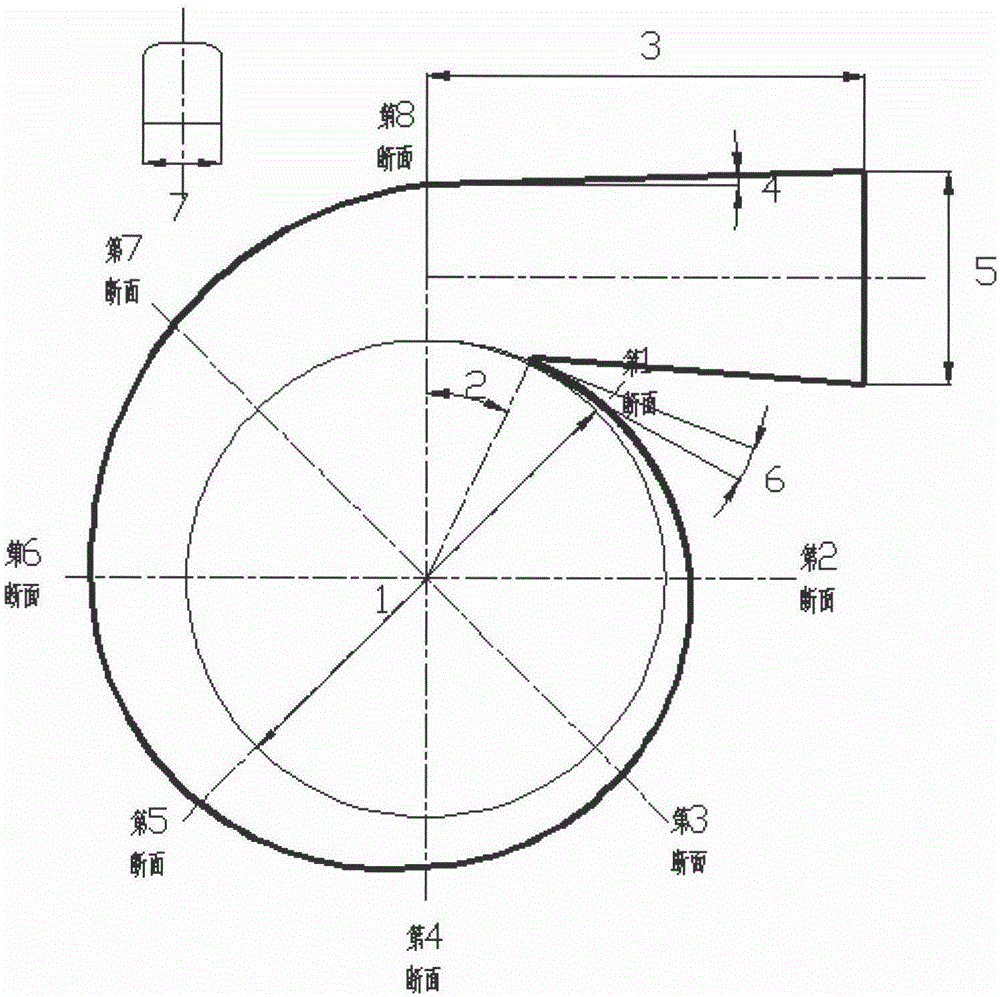
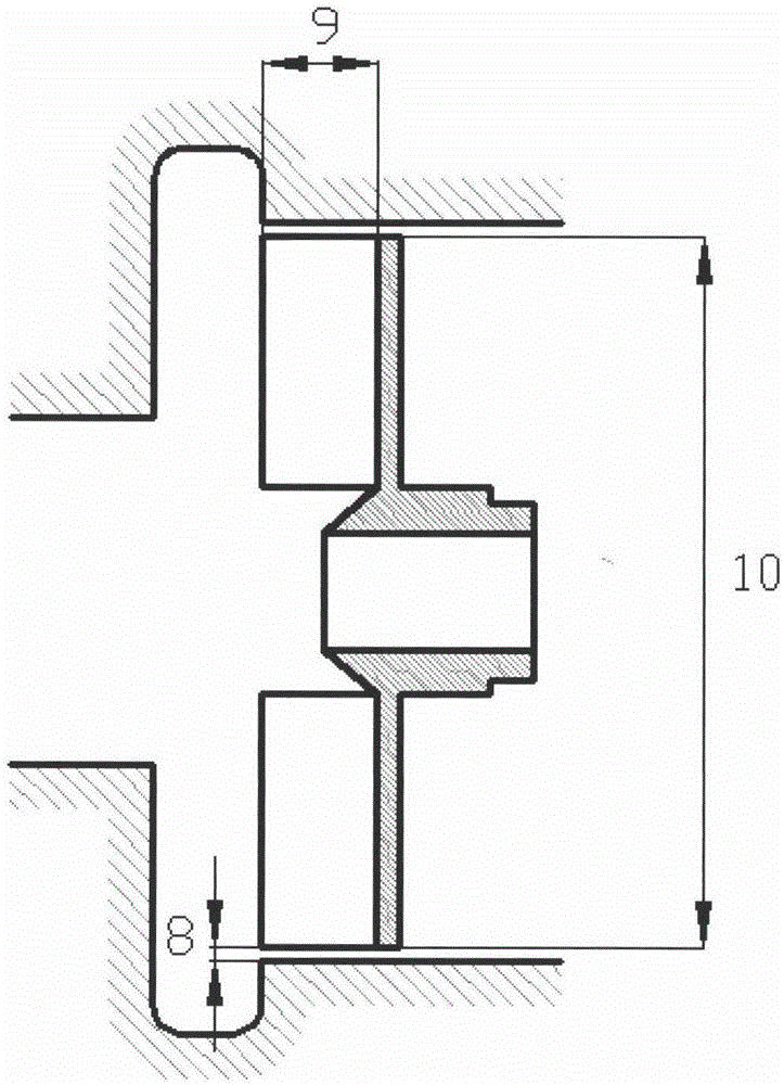
[0071] figure 1 with figure 2 Together determine the shape of the pressurized water chamber of the swirl pump. It can improve the flow condition in the pump, improve the passability of the impurity-containing liquid in the pressure water chamber of the swirl pump and the hydraulic efficiency of the swirl pump. The section of the pressurized water chamber of the present invention is rectangular, and the two corners are transitioned with rounded corners, which is convenient for casting and processing. The arrangement of the diffuser tubes is tangential arrangement, cut at the eighth section. D. d The outlet diameter of the diffuser should be a standard diameter, which is convenient for matching with the existing flange. Satisfy D d When the diameter is the standard and the flow velocity of the medium in the diffusion tube is within the economic flow velocity range, L should be as small as possible to reduce the overall size of the swirl pump overall device. The present in...


PUM


Abstract

The invention relates to a hydraulic design method for an efficient and large-flow vortex pump quasi-annulus pumping chamber. Design formulas of a volute base diameter, a gap between an annular retraction cavity and an impeller, a pumping chamber wrap angle, a separation tongue helix angle, a diffusing pipe diffusion angle and a diffusing pipe height are provided. The vortex pump pumping chamber designed through the design method can well guarantee that a vortex pump is not blocked, the flowing condition inside the pump is improved under the condition that the hydraulic loss is small, the passing ability of the vortex pump pumping chamber for liquid containing impurities is improved, and the hydraulic efficiency of the vortex pump is improved.

Description

technical field [0001] The invention relates to a hydraulic design method of a high-efficiency large-flow swirl pump pressurized water chamber, in particular to a hydraulic design method of a quasi-annular annular pressurized chamber of a swirl pump. Background technique [0002] The main structural feature of the swirl pump is that the impeller retracts in the pump cavity behind the pressurized water chamber, and when the impeller rotates, a through flow and a circulating flow are formed in the vaneless cavity in front of the impeller. The through flow enters the pump chamber through the passage between the impeller blades and flows out, while the circulating flow circulates in the vaneless cavity. Since the middle part of the circulating flow is a low-pressure area, solid particles fall into this area and flow out under the drive of the swirling flow, so most of the solid matter can flow out of the vaneless chamber directly without passing through the impeller. Based on t...

Claims


Application Information

Patent Timeline
IPC IPC(8): F04D29/44
Inventor 付强陈宗良王秀礼朱荣生卢永刚王学吉
Owner JIANGSU UNIV
Why Eureka
Try Eureka