Contact unit for connector

A technology of connectors and contacts, which is applied in the direction of contact parts, etc., can solve the problems of reducing the effect of elastic elements, permanent deformation of pressure springs, and reduction of contact piece pressing force, etc., and achieves small restoring force, small thermal conductivity, and good temperature compensation. Effect

Inactive Publication Date: 2007-07-25
潘敏
View PDF0 Cites 6 Cited by
  • Summary
  • Abstract
  • Description
  • Claims
  • Application Information

AI Technical Summary

Problems solved by technology

However, the surface contact area between the U-shaped pressure spring and the contact finger is large, and the thermal conductivity is large. The heat on the contact finger is easy to spread to the U-shaped pressure spring, which will cause the U-shaped pressure spring to heat and deform, resulting in a decrease in its elastic capacity, which may seriously cause damage to the U-shaped pressure spring. The pressure spring is burned out, and the damage of the pressure spring directly causes the pressing force to the contact piece to drop, which easily causes

Method used


Image

  • Contact unit for connector
  • Contact unit for connector
  • Contact unit for connector

Examples


Example Embodiment

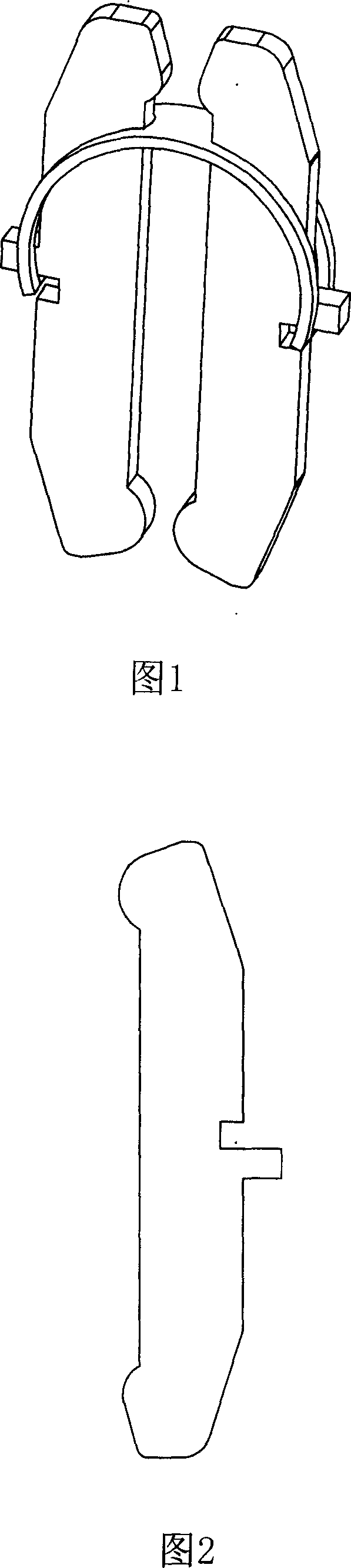
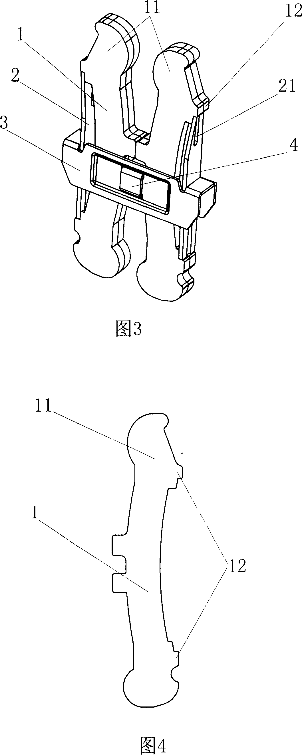
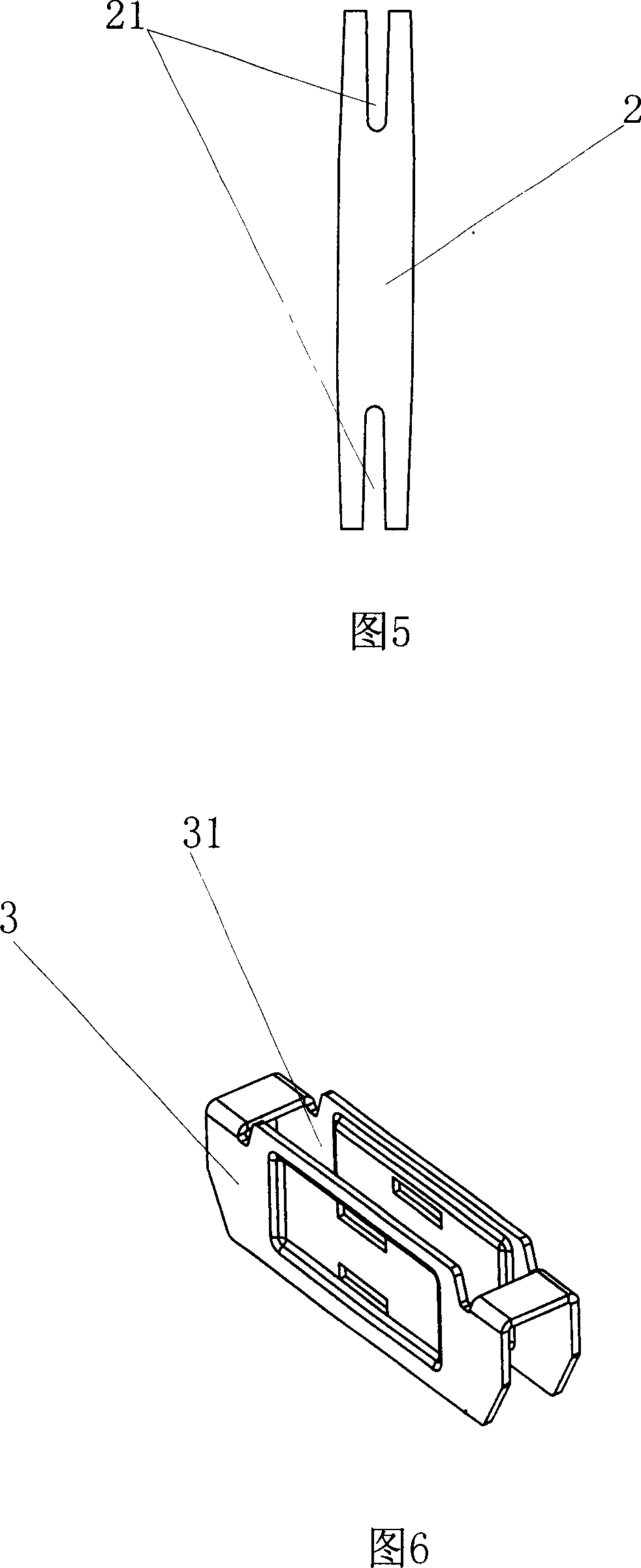
[0014] As shown in Figures 3, 4, 5, and 6, the specific embodiment of the present invention is a contact unit for a connector. The contact unit has two pairs of contact fingers 1, and contact claws at both ends of each contact finger 1 The outer side of 11 is symmetrically provided with bumps 12, the outer end of the contact finger 1 is provided with a linear spring 2 each, both ends of the linear spring 2 form a comb-shaped opening 21, and the two ends of each pressure spring 2 are pressed against The two bumps 12 on the same side of the contact finger 1 constitute the pressure spring of the contact unit. A spring frame 3 is inserted in the middle of the contact unit. The spring frame 3 is provided with the contact finger 1 and the linear spring 2 along the longitudinal direction. For the inserted socket 31, the inner wall of the socket 31 and the linear spring 2 form a limit fit, the center of the spring frame 3 is provided with a pin opening, and the U-shaped pin 4 passes throu...


PUM


Abstract

The contactor unit includes two pair of stylus or more, pressure spring, and lugs setup symmetrically on outside the touch claws at two ends of each stylus. The pressure spring is linear spring. There are comby openings at two ends of linear spring. One pressure spring is setup at each outside end of the stylus. Two ends of each pressure spring are pressed against two lugs at same side of the stylus so as to constitute elastic component of the stylus unit. A spring bracket is socket jointed to middle part of the stylus unit. A plug socket for the stylus and pressure spring to be inserted is setup on the spring bracket along long direction. Position limited fit is formed between inner wall of the plug socket and the pressure spring. Being setup at the middle of the spring bracket, a bolt forms positioning fit together with the stylus. Features are: reasonable structure, compact, and stable working performance of the contactor unit.

Description

technical field [0001] The invention relates to a connector, in particular to a contact unit for the connector. Background technique [0002] The function of the contact unit of the connector is to electrically connect the withdrawable parts of the low-voltage withdrawable switchgear to the connecting piece of the bus bar or other similar components. As shown in Figures 1 and 2, the contact unit in the prior art is composed of multiple pairs of contact fingers, U-shaped pressure springs, etc. There is an end contact on the contact claws at both ends of each contact finger, and each pair of contact fingers Press the two opposite surfaces of the two contact pieces through the end contacts on it, and make the two contact claws approach each other through the action of the U-shaped pressure spring on the contact unit to keep the compression of the connecting piece state. However, the surface contact area between the U-shaped pressure spring and the contact finger is large, and...

Claims


Application Information

Patent Timeline
IPC IPC(8): H01R13/15
Inventor 潘敏
Owner 潘敏
Why Eureka
Try Eureka