Bolt falling preventive structure and hold ring

A technology for retaining rings and bolts, applied in the directions of bolts, nuts, connecting components, etc., can solve the problems of increasing particles, increasing production costs, increasing component parts, etc., and achieves the effect of simple processing

Active Publication Date: 2007-07-25
CKD
View PDF2 Cites 7 Cited by
  • Summary
  • Abstract
  • Description
  • Claims
  • Application Information

AI Technical Summary

Problems solved by technology

Therefore, it is necessary to increase the number of components and processing, resulting in an increase in production costs
Also, since it is a device used in a clean room, it is not desirable to add irregularities on the flange surface where particles and the like tend to stay.

Method used


Image

  • Bolt falling preventive structure and hold ring
  • Bolt falling preventive structure and hold ring
  • Bolt falling preventive structure and hold ring

Examples


no. 1 example

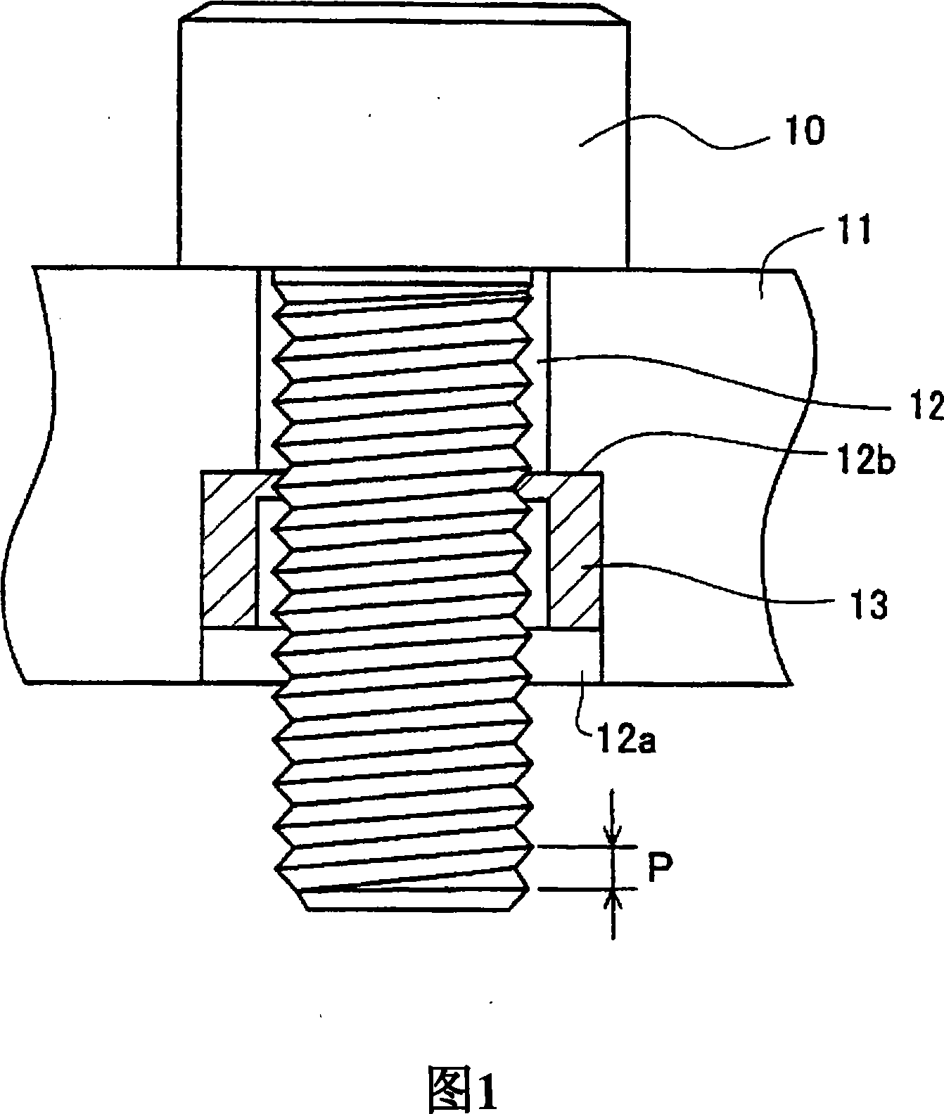
[0087] Fig. 1 is a front partial cross-sectional view of a bolt drop-off prevention mechanism and a retaining ring of the present invention, specifically, a module of a gas integration unit used in a semiconductor manufacturing device, that is, an on-off valve, a flow meter, and a fixed body. A cross-sectional view of a plurality of threaded through-holes 12 serving as mounting holes on a mounting flange portion 11 of a mass flow controller or the like. By inserting the main body fixing bolts 10 into the threaded through holes 12 (hereinafter referred to as the threaded through holes 12 ) serving as mounting holes, the above-mentioned modules are mounted on an unillustrated mounting rail or flow path block.

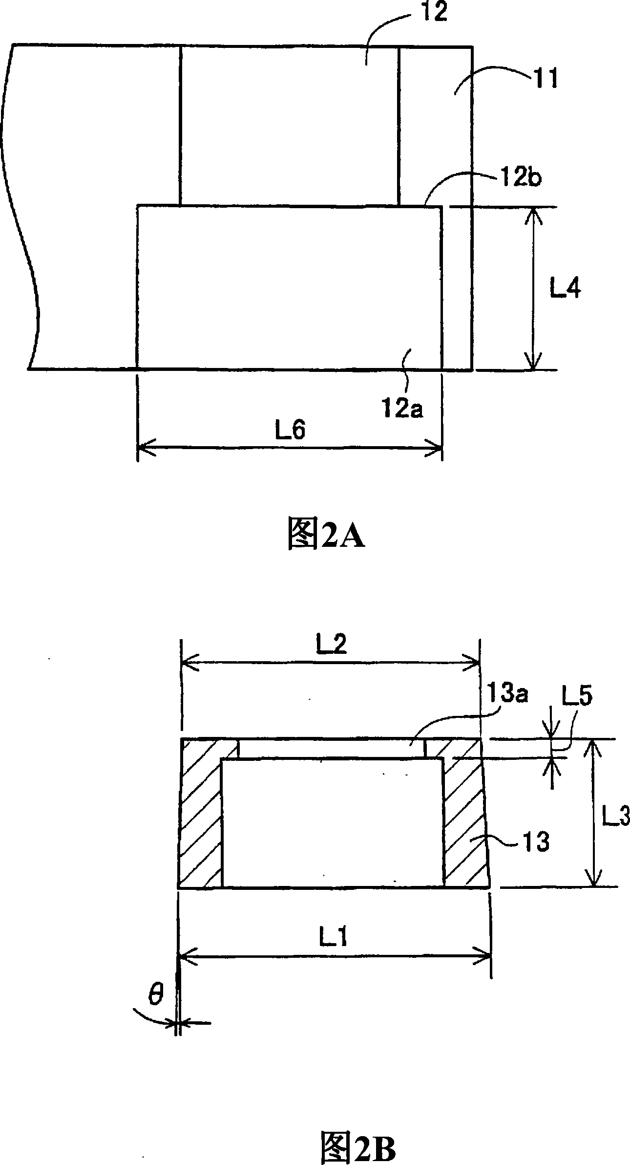
[0088] FIG. 2 is a partial detailed view and a component view thereof. A plurality of threaded through holes 12 as shown in FIG. 2A are provided on the mounting flange 11 of the on-off valve and the mass flow controller of the module as the gas integration unit, and on th...

no. 2 example

[0099] Next, a second embodiment of the present invention will be described.

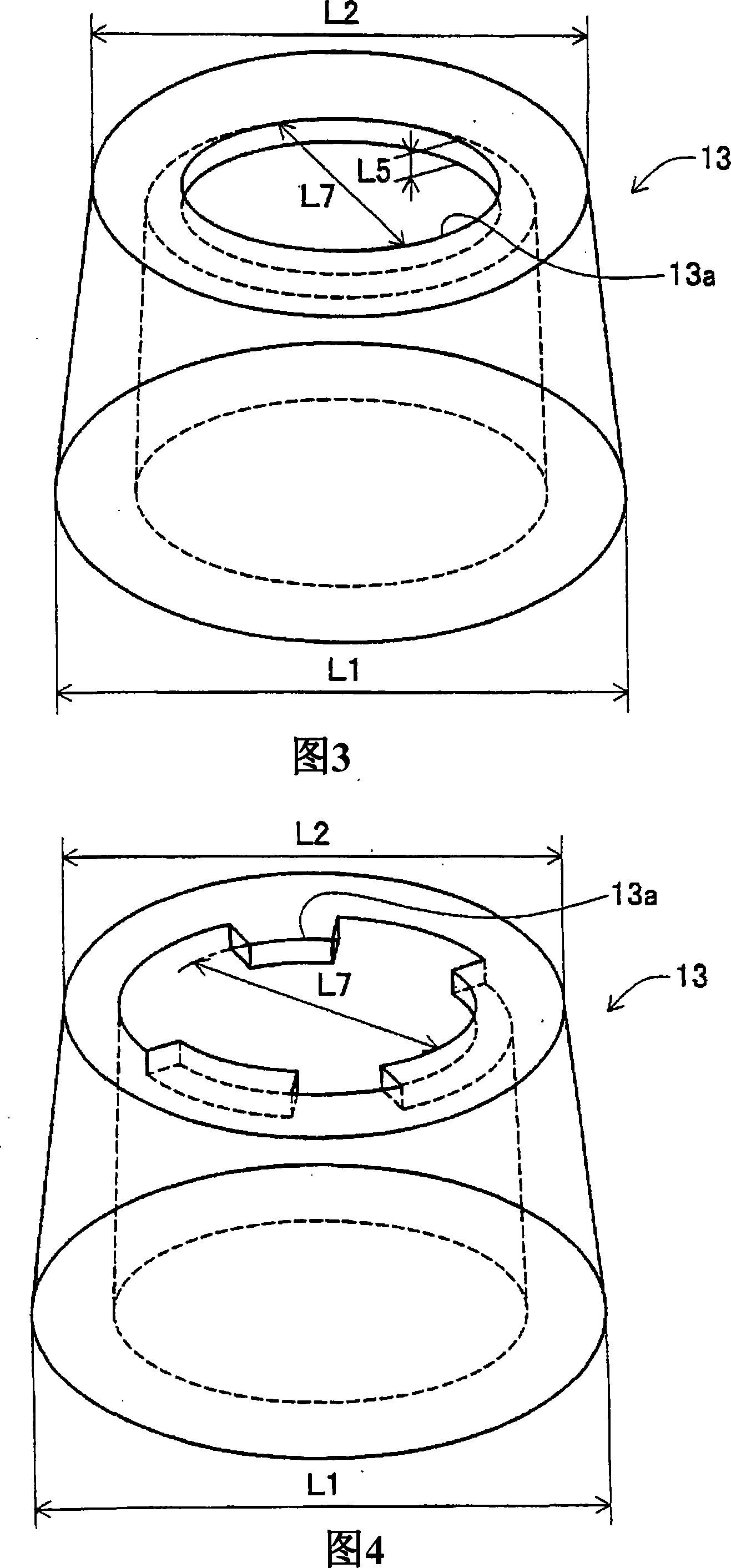
[0100] Figure 3 shows a perspective view of the first embodiment; Figure 4 shows a perspective view of the second embodiment.

[0101] The retaining ring 13 of the second embodiment has substantially the same outer shape as the retaining ring 13 of the first embodiment, but the shape of the portion of the bolt engaging portion 13a is different. The bolt engaging portion 13a of the second embodiment is not a simple circle, but has cutouts at three places, and the contact area between the bolt engaging portion 13a and the main body fixing bolt 10 is reduced. That is, the bolt engaging portion 13 a is constituted by three substantially trapezoidal protrusions, and one side of the substantially trapezoidal protrusions is in diametric contact with the bottom of the external thread portion of the main body fixing bolt 10 . In addition, the thickness L5 of the bolt engaging portion 13a is the same as that...

no. 3 example

[0111] Next, a third embodiment of the present invention will be described.

[0112] FIG. 5 shows a top view of the third embodiment; FIG. 6 shows a cross-sectional view of the third embodiment.

[0113] In the third embodiment, although the holding ring 13 of the first embodiment has substantially the same substantially cylindrical outer shape, the bolt engaging portion 13a serving as a member for holding the main body fixing bolt 10 is different from that of the second embodiment. Unlike the bolt engaging portion 13 a of the example, the width of the thickness L5 is larger than the pitch of the bolts of the main body fixing bolts 10 . In the third embodiment, the thickness L5 of the bolt engaging portion 13 a is set to be at least twice the pitch of the main body fixing bolt 10 .

[0114] The shape of the bolt engaging portion 13a is not a simple circle, but three notches are provided, and the contact area between the bolt engaging portion 13a and the main body fixing bolt ...


PUM


Abstract

A bolt falling preventive structure and a hold ring used for a semiconductor manufacturing apparatus, enabling the easy extraction and insertion of the bolt while maintaining a necessary holding force, and manufacturable at low cost. A seat hole (12a') with a diameter larger than that of a screw insert hole (12) is formed in the surface of a fixed body, in which the screw insert hole (12) for passing a body fixing bolt (10) therein is formed, on the opposite side of the surface thereof in contact with the head of the body fixing bolt (10). The hold ring (13) formed in a cylindrical shape on the outer periphery, having a rear end part with a diameter larger than the inner diameter of the seat hole (12a), having a tip part with a diameter equal to or smaller than the inner diameter of the seat hole (12a), and having, at the tip part, a bolt engagement part (13a) engaged with the ridge part of the body fixing bolt (10) is fitted to the seat hole (12a). Thus, the body fixing bolt (10) can be prevented from falling.

Description

technical field [0001] The present invention relates to a bolt drop prevention structure and a retaining ring for preventing the bolt from falling off by being attached to a threaded through hole as an attachment hole of a fixed body in which a threaded through hole through which a bolt passes is formed. Background technique [0002] For example, gas integrated units used in semiconductor manufacturing equipment are often used in a state of being hung on a wall in order to require a higher degree of integration than before. Therefore, the bolts used for fixing the components are often screwed in horizontally or from below. [0003] Therefore, in the method disclosed in patent document 1, the method of improving workability by temporarily fixing a bolt is taken. [0004] As shown in the figure of patent document 1, the enlarged detailed view is shown in FIG. 12, and it demonstrates below. [0005] The bolt shaft through hole 112 provided on the mounting flange portion 11 of...

Claims


Application Information

Patent Timeline
Patent Type & Authority Applications(China)
IPC IPC(8): F16B41/00
CPCF16B41/002F16B41/00
Inventor 青山达人佐藤正义
Owner CKD
Why Eureka
Try Eureka