Dynamic pressure bearing device

A technology of dynamic pressure bearings and thrust bearings, which is applied in the direction of sliding contact bearings, bearings, rotating bearings, etc., can solve the problems of high cost, achieve low cost, high bearing performance, and maintain the effect of bearing performance

Inactive Publication Date: 2007-07-25
NTN CORP
View PDF2 Cites 9 Cited by
  • Summary
  • Abstract
  • Description
  • Claims
  • Application Information

AI Technical Summary

Problems solved by technology

Additionally, it leads to exorbitant costs

Method used


Image

  • Dynamic pressure bearing device
  • Dynamic pressure bearing device
  • Dynamic pressure bearing device

Examples


Embodiment Construction

[0030] In the following, embodiments of the present invention will be described with reference to the drawings.

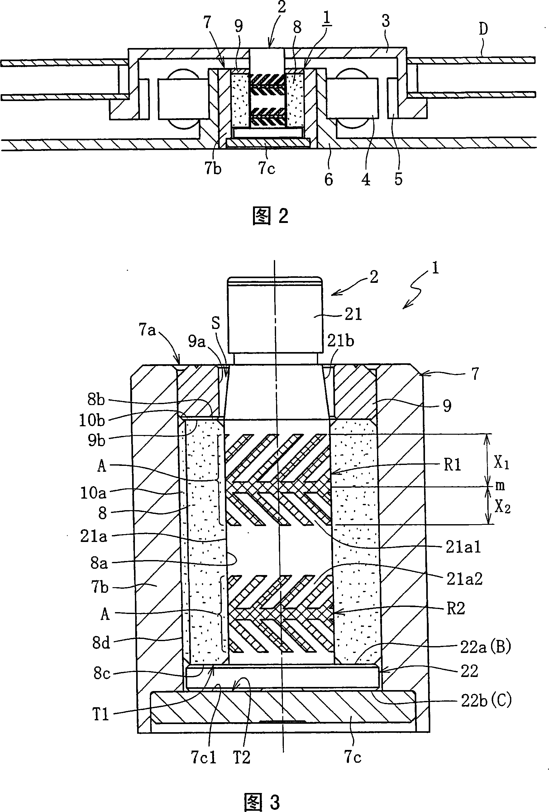
[0031] FIG. 2 shows an example of the structure of a spindle motor for an information device, in which a fluid dynamic pressure bearing device 1 according to the present invention is incorporated. This spindle motor is used in a disk drive device such as an HDD, and the spindle motor is equipped with: a fluid dynamic pressure bearing device 1, a disk hub 3 mounted on a shaft member 2 of the fluid dynamic pressure bearing device 1, a The stator coil 4 and the rotor magnet 5, and the bracket 6 are opposed to each other through the medium of the gap. The stator coil 4 is mounted on the outer periphery of the bracket 6 , and the rotor magnet 5 is mounted on the inner periphery of the hub 3 . The hub 3 holds one or more disks D such as magnetic disks in its outer periphery. Furthermore, the housing 7 of the fluid dynamic bearing device 1 is mounted on the inner periph...


PUM


Abstract

A dynamic pressure bearing device having a shaft member with high strength and capable of maintaining high bearing performance is provided at low cost. A shaft blank (23) integrally has a shaft section (23a) formed of a material having higher strength than resin and a projection section (23b) projecting toward the outer diameter side of the shaft section (23a). A shaft member (2) has the shaft blank (23) and a resin section (24) that covers at least one end surface of the projection section (23b) of the shaft blank (23) and faces a thrust bearing clearance.

Description

technical field [0001] The invention relates to a fluid dynamic pressure bearing device. Background technique [0002] A hydrodynamic bearing device is a bearing device having a mechanism for supporting a shaft member in a non-contact manner by the action of dynamic pressure of a fluid (lubricating fluid) generated in a bearing gap. This fluid dynamic pressure bearing device has various features such as high-speed rotation, high rotation accuracy, and low noise, and is suitable as a bearing used in a spindle motor of a magnetic disk drive in an information device, such as Magnetic disk device such as HDD or FDD, optical disk device such as CD-ROM, CD-R / RW or DVD-ROM / RAM, or magneto-optical disk device such as MD or MO, polygon scanning motor ( polygonscanner motor), or small motors for projector color wheels, axial fans, etc. [0003] Examples of the hydrodynamic bearing device include a type in which a radial bearing part is formed of a hydrodynamic bearing and a thrust b...

Claims


Application Information

Patent Timeline
Patent Type & Authority Applications(China)
IPC IPC(8): F16C33/20F16C17/10F16C33/14H02K5/167H02K7/08
CPCG11B19/2009F16C3/02F16C17/107F16C33/107F16C2370/12H02K5/1675H02K7/08F16C33/1075F16C17/02F16C17/10F16C33/14F16C33/20
Inventor 古森功日比建治山本康裕
Owner NTN CORP
Why Eureka
Try Eureka