Pressurizing machine

一种增压机、压缩机的技术,应用在机械设备、发动机元件、燃气轮机装置等方向,能够解决密封部件作业性差、不方便等问题,达到提高密封性、简单安装作业的效果

Active Publication Date: 2007-08-01
IHI CORP
View PDF1 Cites 18 Cited by
  • Summary
  • Abstract
  • Description
  • Claims
  • Application Information

AI Technical Summary

Problems solved by technology

In addition, it is necessary to install the sealing member 49 before assembling the sealing case 53 in the supercharger, which is inconvenient since the sealing member 49 cannot be installed thereafter.
[0019] Therefore, in Patent Document 1, the workability at the time of mounting the sealing member 49 is poor.

Method used


Image

  • Pressurizing machine
  • Pressurizing machine
  • Pressurizing machine

Examples


Embodiment Construction

[0053] Preferred embodiments of the present invention are described with reference to the drawings. In addition, the same code|symbol is used for the common part in each figure, and a repeated description is abbreviate|omitted.

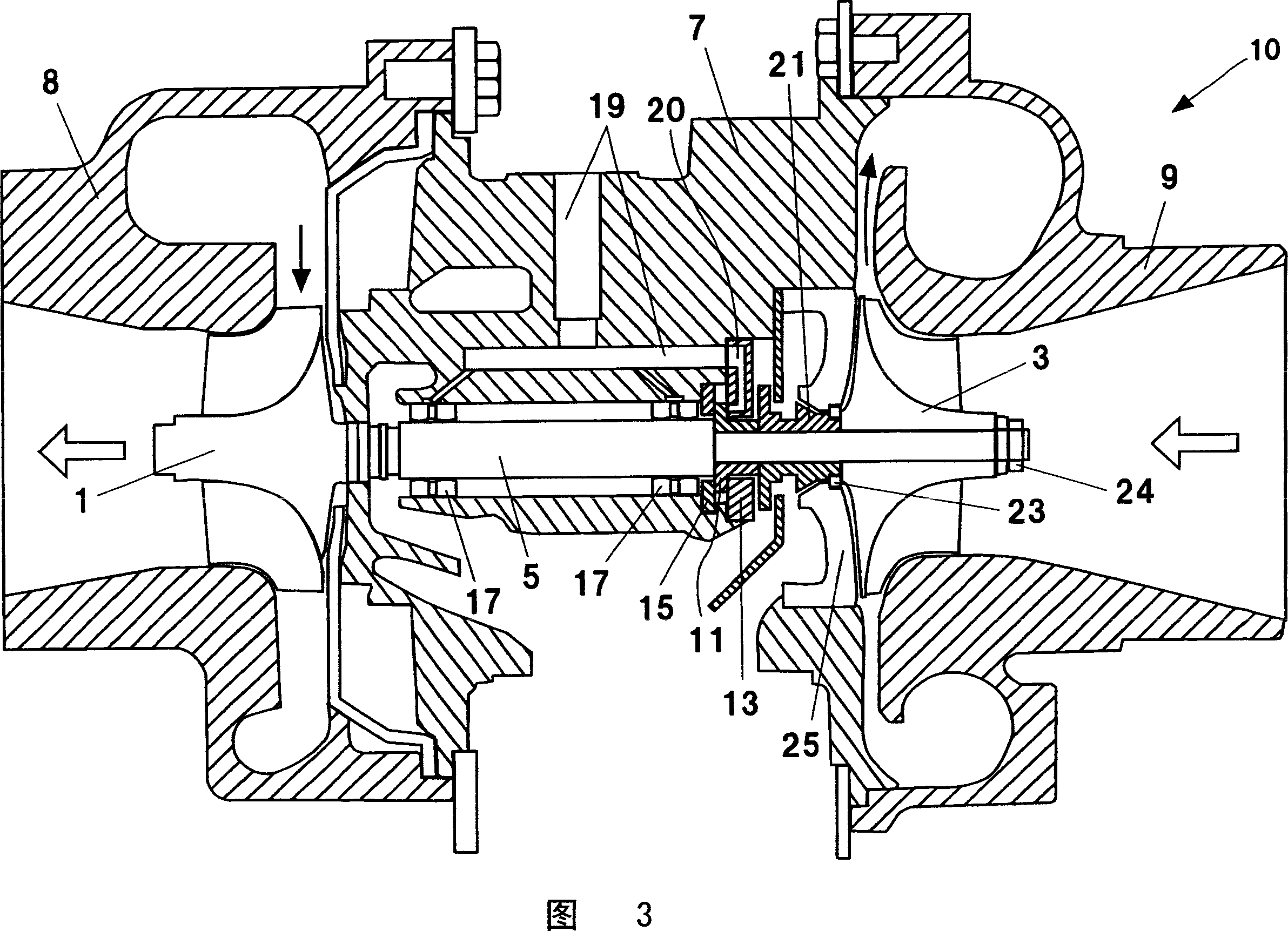
[0054] 3 is a longitudinal sectional view of the supercharger according to the embodiment of the present invention cut along the axial direction, showing the overall configuration of the supercharger. As shown in FIG. 3 , the supercharger 10 according to the present embodiment includes: a turbine impeller 1 driven to rotate by exhaust gas; a compressor impeller 3 driven to compress air by rotation of the turbine impeller 1; connected to the turbine impeller 1 and the rotating shaft 5 of the compressor impeller 3; the housing 7 of the bearing structure that rotatably supports the rotating shaft 5 is assembled inside.

[0055] In the example of FIG. 3 , the housing 7 is a bearing housing separated from the turbine housing 8 housing the turbine wheel 1 ...


PUM


Abstract

An oil seal structure of a supercharger (10) has an oil shield member (21), a seal housing (25), and an annular seal member (23) arranged between the oil shield member (21) and the seal housing (25). The oil shield member (21) has a portion in which an approximately circular outer edge is formed in a vertical cross section to an axial direction, in a leading end portion in a compressor side, and the oil shield member (21) has an outer edge reduced-diameter portion (21a) which is formed in the leading end in the compressor side and in which a radius of the outer edge is smaller than the other portions of the outer edge. The seal member (23) is fitted to the outer edge reduced-diameter portion (21a). An opening through which the oil shield member (21) passes is formed in the seal housing (25), and the seal housing (25) is brought into contact with the seal member (23) in an inner edge in a radial direction forming the opening.

Description

technical field [0001] The present invention relates to superchargers. Background technique [0002] The basic configuration of a supercharger includes a turbine having a turbine wheel rotated by exhaust gas from the engine, and a compressor having a compressor wheel rotated by the turbine wheel. In addition, in order to transmit the rotational driving force from the turbine to the compressor, the turbocharger is equipped with a rotary shaft that connects the turbine impeller and the compressor. [0003] With such a configuration, the turbine impeller is rotated by exhaust gas from the engine, and at the same time, the compressor impeller is also rotationally driven, whereby compressed air can be supplied from the compressor to the engine. As a result, the engine is brought into a supercharged state higher than the naturally aspirated state, and the engine is brought into a high output state. [0004] In order to rotatably support the rotating shaft, a bearing structure is...

Claims


Application Information

Patent Timeline
Patent Type & Authority Applications(China)
IPC IPC(8): F02B39/00F16J15/16
CPCF02C7/28F16C2360/24F01D25/186F05D2220/40F01D11/003F02B39/00F02B39/14F16C17/04
Inventor 清水政宏高桥幸雄
Owner IHI CORP
Why Eureka
Try Eureka