Speed reducer with mutipurpose interface
A technology of reducers and connecting parts, which is applied in the direction of couplings, rigid shaft couplings, transmission parts, etc., to reduce the backlog of production and inventory, simplify design, and shorten the design cycle.
- Summary
- Abstract
- Description
- Claims
- Application Information
AI Technical Summary
Problems solved by technology
Method used
Image
Examples
Embodiment Construction
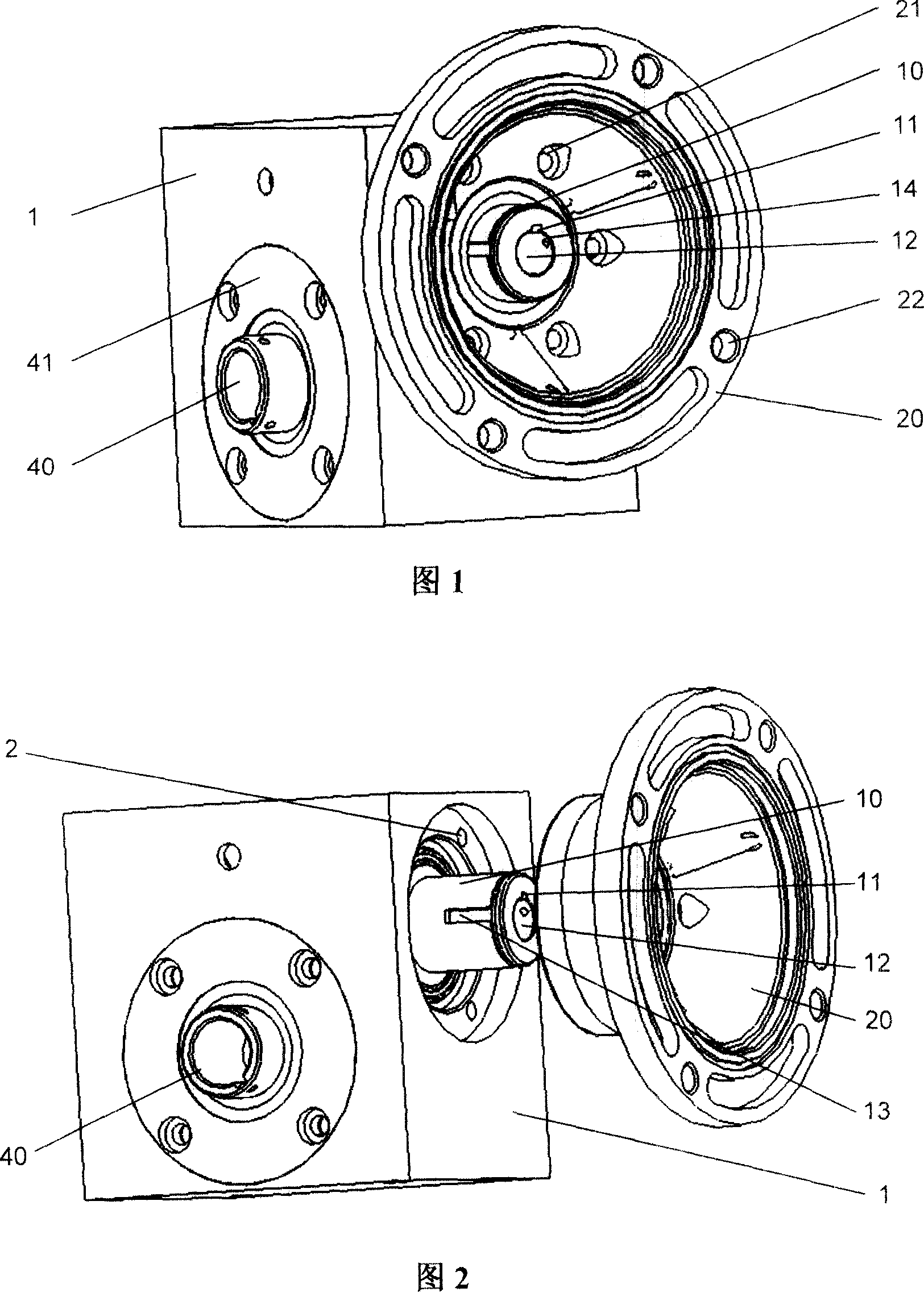
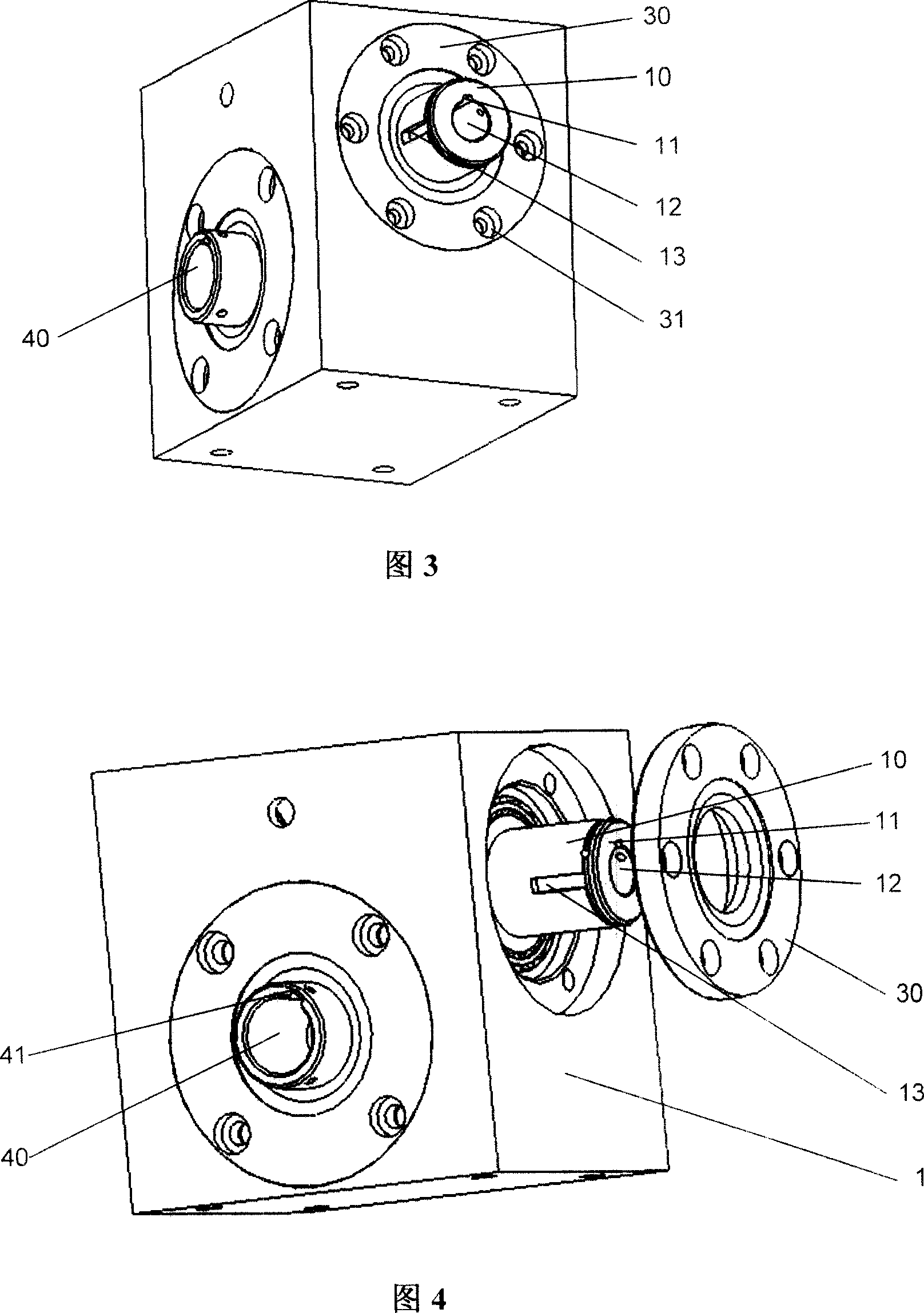
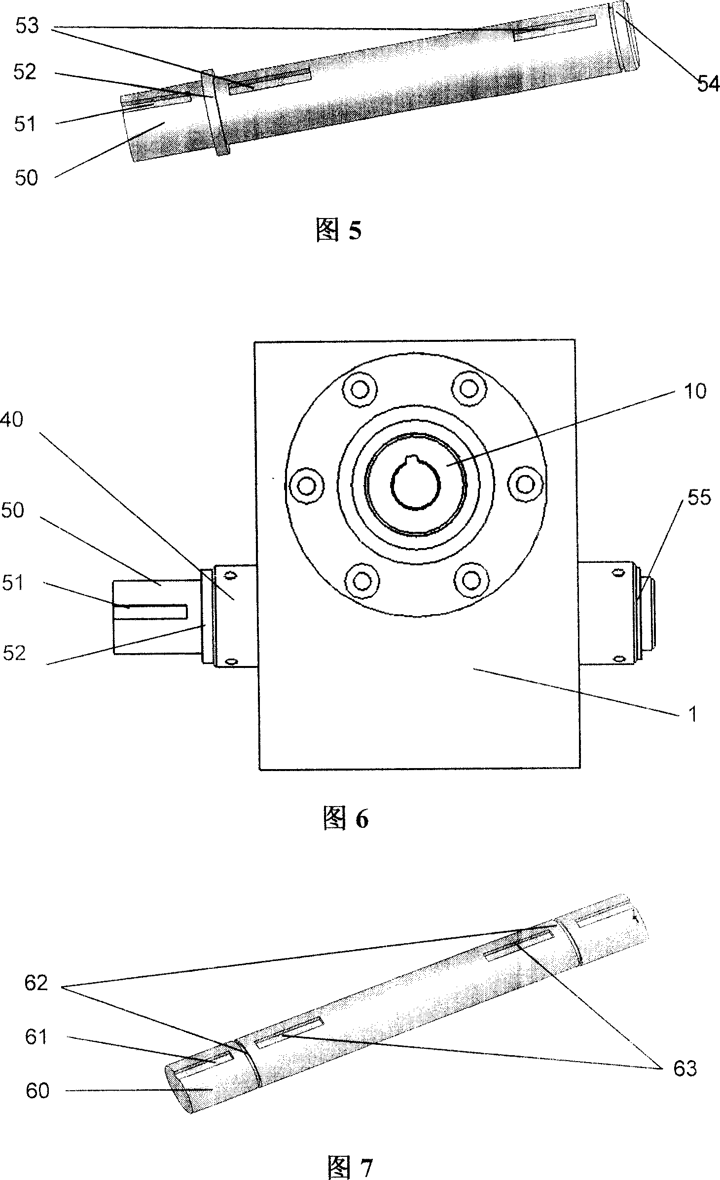
[0034] Figures 1 to 8 illustrate an embodiment of the interface design of the reducer of the present invention.
[0035] Figure 1 and Figure 2 describe the input structure of the reducer connected with the C-type interface. This structure is usually used when the input shaft of the reducer is coaxial with the output shaft of the power equipment. This reducer has a casing 1, which is a box body, to facilitate fixing and install reduction devices such as worm gears or gear sets, etc., and the casing 1 is also a base for the input shaft 10 and the output shaft 40, and The input shaft 10 and the output shaft 40 are to be connected to corresponding parts of the internal mechanism, respectively. On the input side of the casing 1, the input shaft 10 protrudes to connect the high-speed shaft from the electric motor, internal combustion engine or other power equipment, and the outer end of the input shaft 10 is provided with a hollow hole 12 whose diameter and depth meet the correspon...
PUM
 Abstract
Description
Claims
Application Information
 - R&D
- Intellectual Property
- Life Sciences
- Materials
- Tech Scout
- Unparalleled Data Quality
- Higher Quality Content
- 60% Fewer Hallucinations
Browse by: Latest US Patents, China's latest patents, Technical Efficacy Thesaurus, Application Domain, Technology Topic, Popular Technical Reports.
© 2025 PatSnap. All rights reserved.Legal|Privacy policy|Modern Slavery Act Transparency Statement|Sitemap|About US| Contact US: help@patsnap.com


