

Method and device for measuring the distance by ultrasonic waves
A technology for measuring distance and ultrasonic waves, applied in the field of measuring distance, can solve the problems of affecting the measurement accuracy, inaccurate confirmation of the received echo time, etc., and achieve the effect of improving the measurement accuracy
- Summary
- Abstract
- Description
- Claims
- Application Information
AI Technical Summary
Problems solved by technology
Method used
Image

Examples
specific Embodiment approach 1
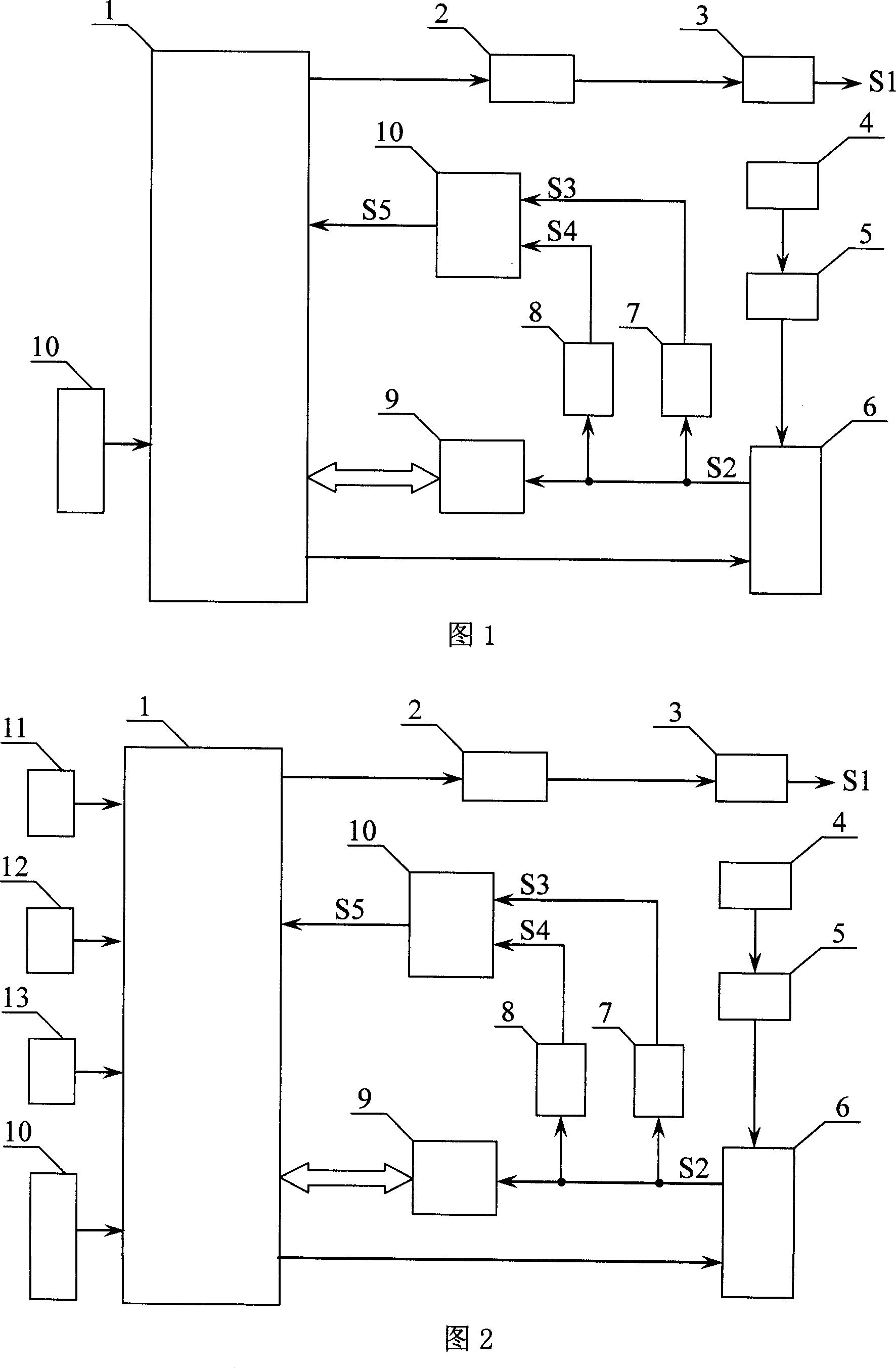
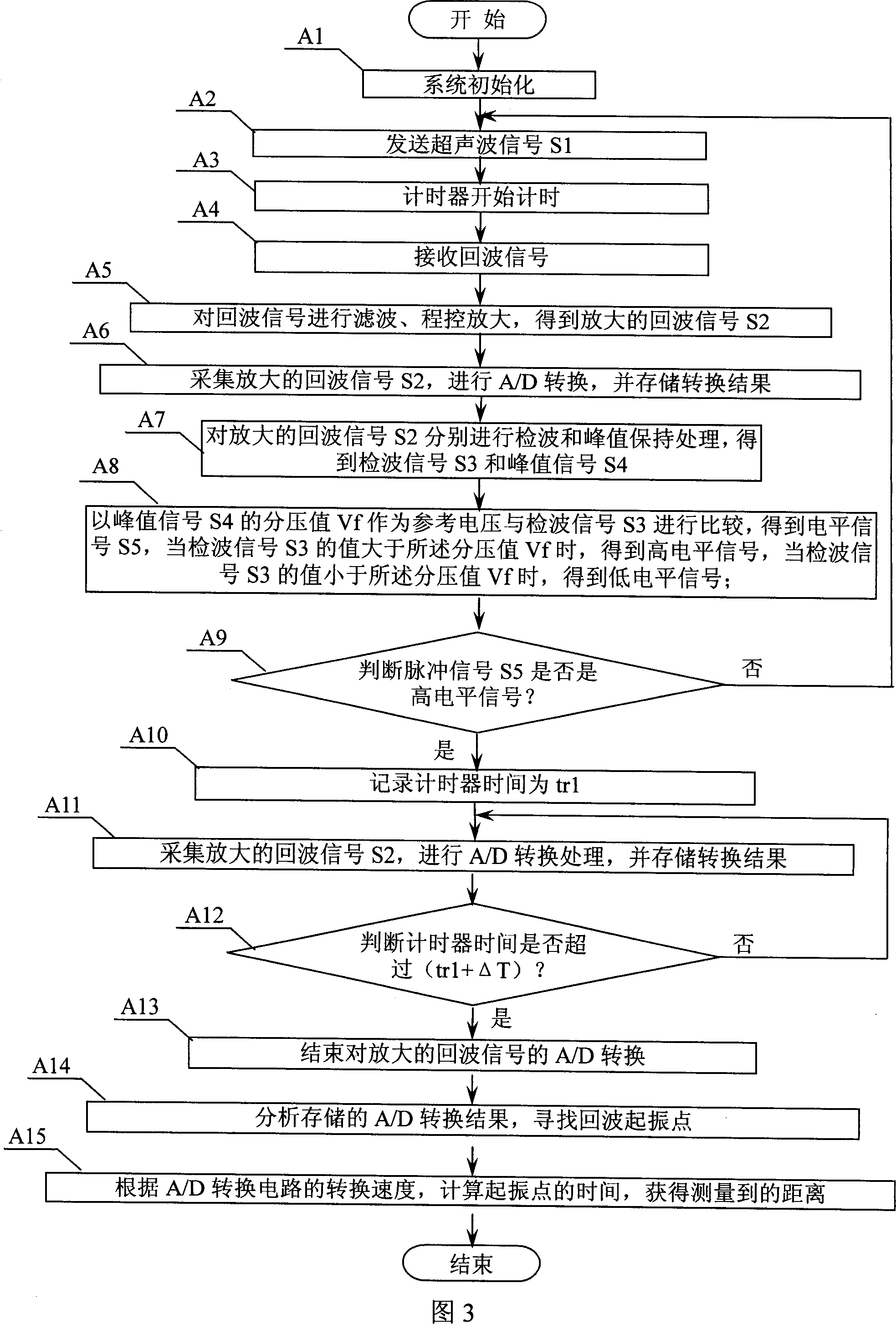
[0022] Specific Embodiment 1: Refer to FIG. 1 , FIG. 3 , and FIG. 5 to illustrate this embodiment. The method for ultrasonic distance measurement of the present embodiment includes:
[0023] Step A1: System initialization;
[0024] Step A2: sending ultrasonic signal S1;
[0025] Step A3: The timer starts timing;
[0026] Step A4: receiving the echo signal;
[0027] Step A5: Filtering and program-controlled amplification of the echo signal to obtain the amplified echo signal S2;
[0028] Step A6: collecting the amplified echo signal S2, performing A / D conversion, and storing the conversion result;
[0029] Step A7: Perform detection and peak hold processing on the amplified echo signal S2 respectively to obtain detection signal S3 and peak signal S4;
[0030] Step A8: Use the divided voltage value Vf of the peak signal S4 as a reference voltage to compare with the detection signal S3 to obtain a level signal S5. When the value of the detection signal S3 is greater than the...
specific Embodiment approach 2
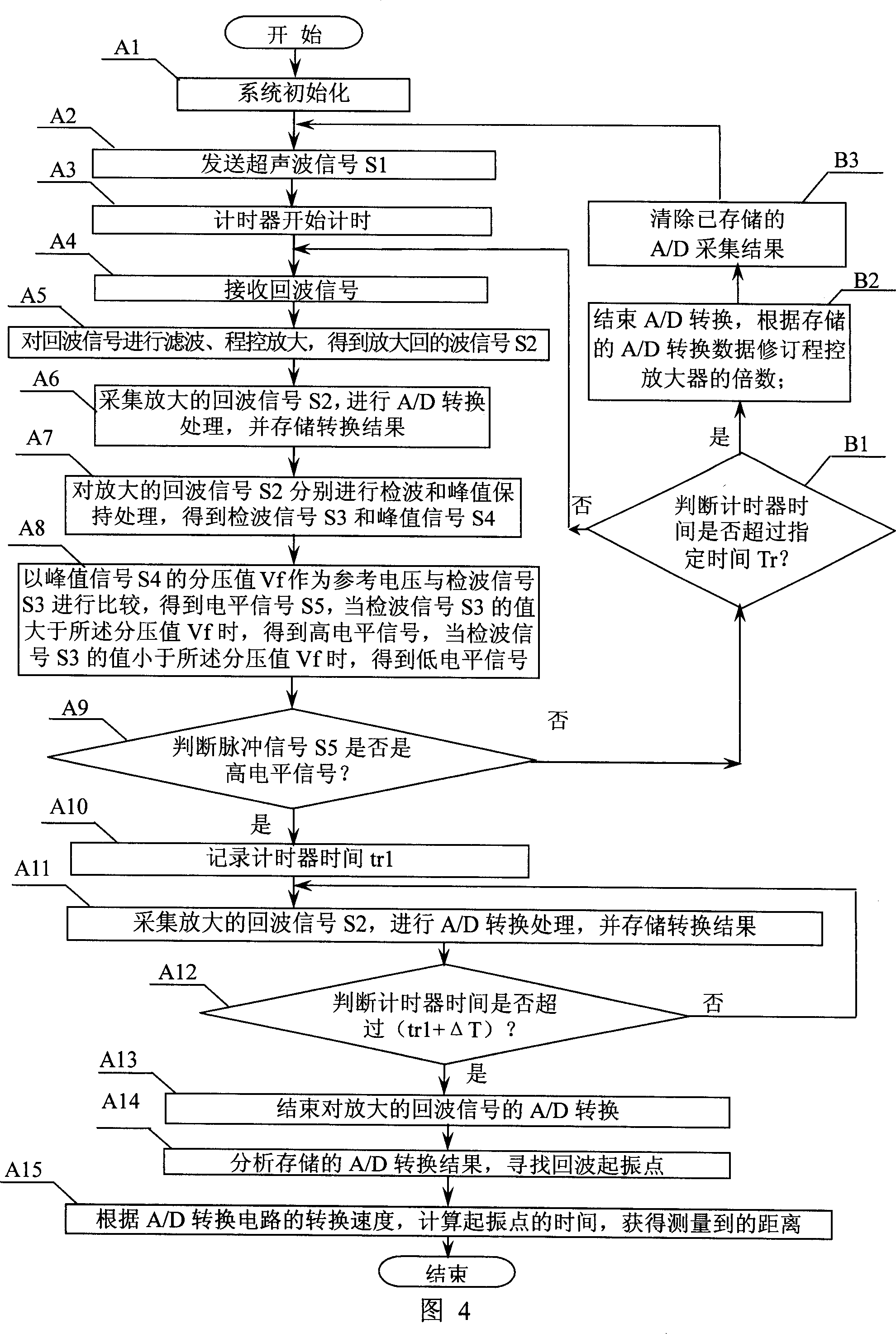
[0046] Specific embodiment two: refer to Fig. 4 and illustrate this embodiment, the difference with the method for the ultrasonic measurement distance of specific embodiment one is, in step A9, if the judgment result is no, then carry out following step B1:
[0047] Step B1: Determine whether the timer time exceeds the specified time Tr, if the judgment result is yes, then execute step B2; if the judgment result is no, then return to execute step A4;
[0048] Step B2: End the A / D conversion, and revise the multiple of the program-controlled amplifier according to the stored A / D conversion data;
[0049] Step B3: Clear the stored A / D acquisition results and return to Step A2.
[0050] In this embodiment, the limitation on the maximum value of the echo time is added. When the waiting time for the pulse signal S5 exceeds the specified time Tr, the echo signal is considered to be too weak and the measurement fails. According to the collected and stored A / D result information In t...
specific Embodiment approach 3
[0053] Embodiment 3: The difference from the method of ultrasonic distance measurement in Embodiment 1 or Embodiment 2 is that after step A15, step A16 is added: correcting the calculated distance according to the external temperature.
[0054] The difference between the device for implementing the method for ultrasonic distance measurement in this embodiment and the device described in Embodiment 1 is that a temperature measurement circuit 10 is added, and the signal output end of the temperature measurement circuit 10 is connected to the signal input end of the CPU control circuit 1 .
[0055] The temperature measurement circuit 10 in this embodiment uses a digital temperature sensor 18 B20.
[0056] The ultrasonic measurement method of this embodiment has a temperature correction function, and can correct the measurement result according to the temperature of the external environment.
PUM
 Abstract
Description
Claims
Application Information