Combined dodging and color separation lighting method and component thereof
A lighting method and technology for lighting components, which are applied to optical components, optics, instruments, etc., can solve the problems of difficult coating of dichroic mirrors, low color separation efficiency, and complex optical paths of components, and achieve high light transmission efficiency and color separation efficiency. , flexible structure, small volume effect
- Summary
- Abstract
- Description
- Claims
- Application Information
AI Technical Summary
Problems solved by technology
Method used
Image

Examples
Embodiment 1
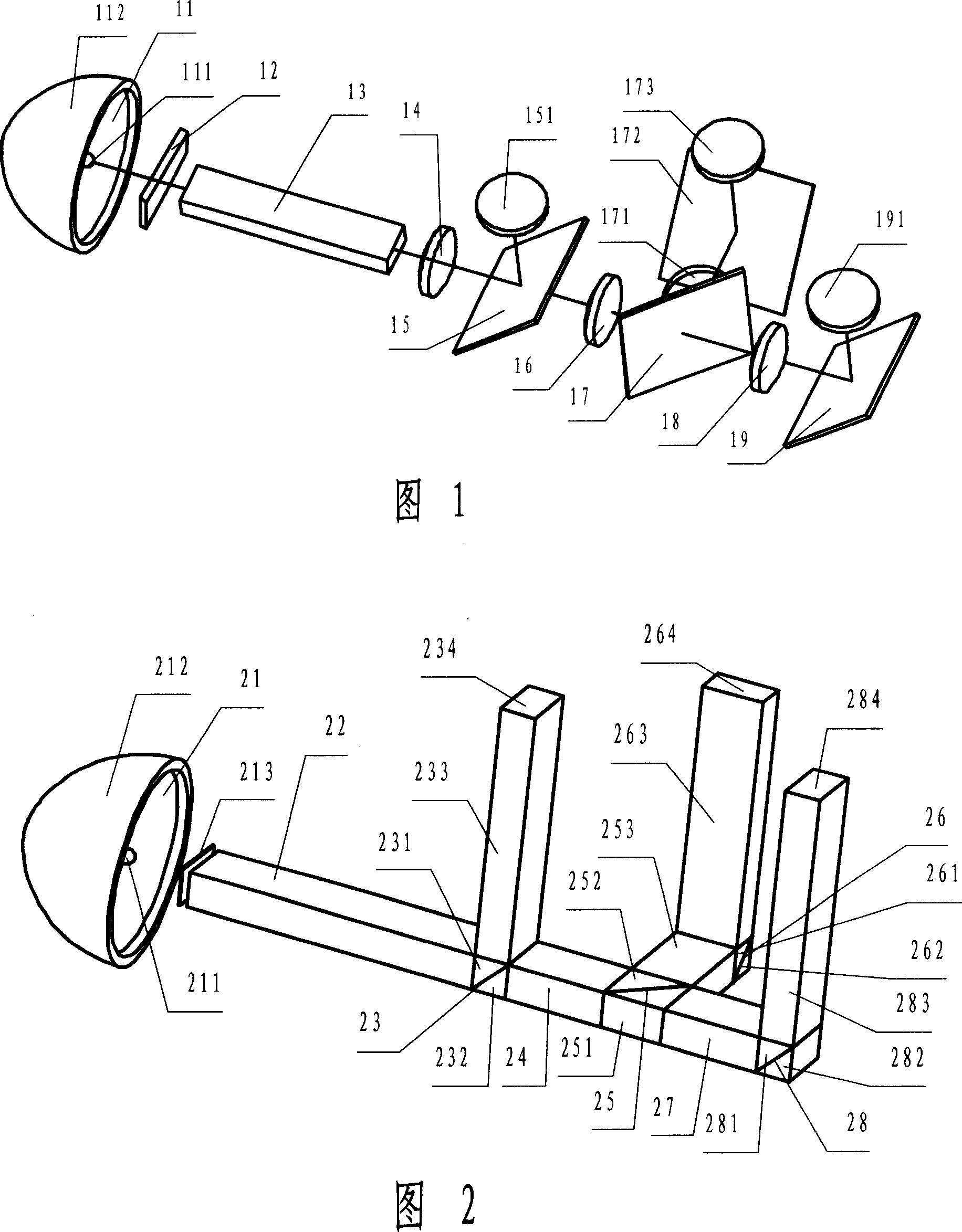
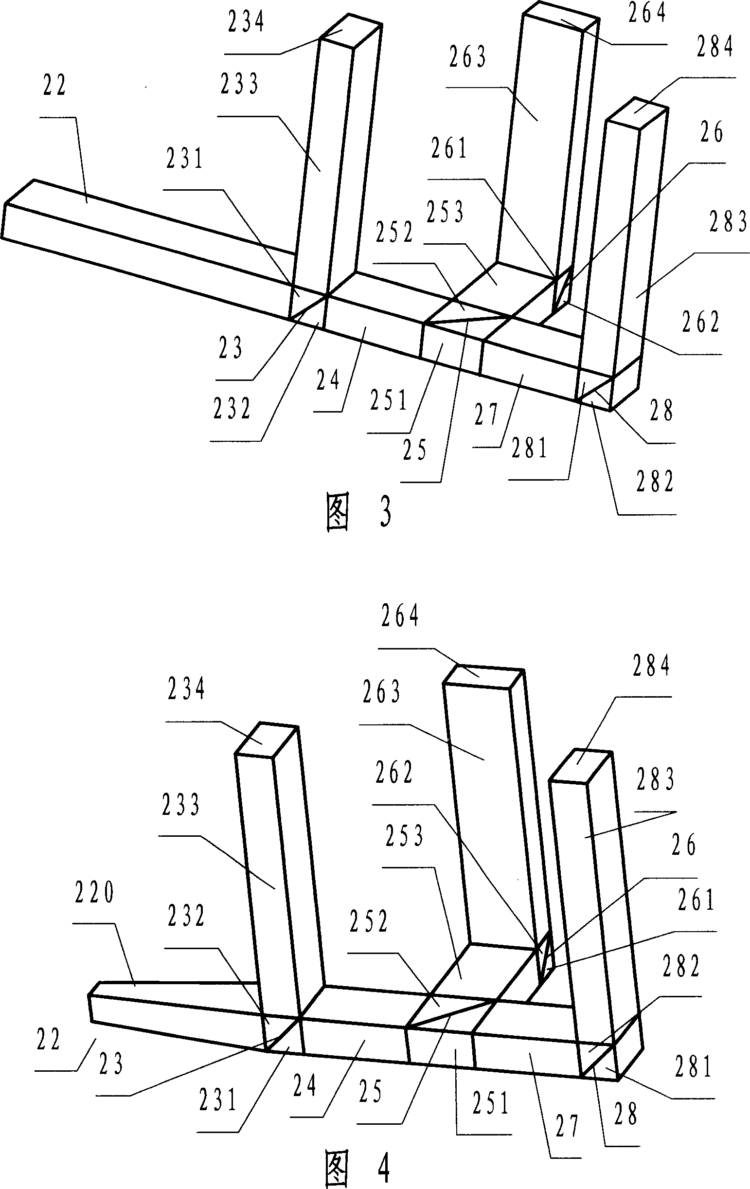
[0034] The assembly of this embodiment has the structure shown in FIG. 3 . The light guide rods, dichroic prisms, and reflective ribs constituting the components of this embodiment are made of optical glass, and the incident light guide rod 22 is a straight prism. Incident light guide rod 22, first connection light guide rod 24, second connection light guide rod 253, third connection light guide rod 27, first exit light guide rod 233, second exit light guide rod 263, third exit light guide rod The cross-section of the light rod 283 is rectangular, the dichroic film of the first dichroic prism 23 reflects blue light, transmits green light and red light, the dichroic film of the second dichroic prism 25 reflects green light, transmits red light, and the first reflective prism The reflective film of the second reflective prism 26 reflects green light, and the reflective film of the second reflective prism 28 reflects red light.
Embodiment 2
[0036] The assembly of this embodiment has the structure shown in FIG. 3 . The light guide rods, dichroic prisms, and reflective ribs constituting the components of this embodiment are made of optical glass, and the incident light guide rod 22 is a straight prism. Incident light guide rod 22, first connection light guide rod 24, second connection light guide rod 253, third connection light guide rod 27, first exit light guide rod 233, second exit light guide rod 263, third exit light guide rod The cross-section of the light rod 283 is rectangular, the dichroic film of the first dichroic prism 23 reflects red light, transmits green light and blue light, the dichroic film of the second dichroic prism 25 reflects green light, and transmits blue light, and the first reflective prism 26 The reflective film of the second reflective prism 28 reflects green light, and the reflective film of the second reflective prism 28 reflects blue light.
Embodiment 3
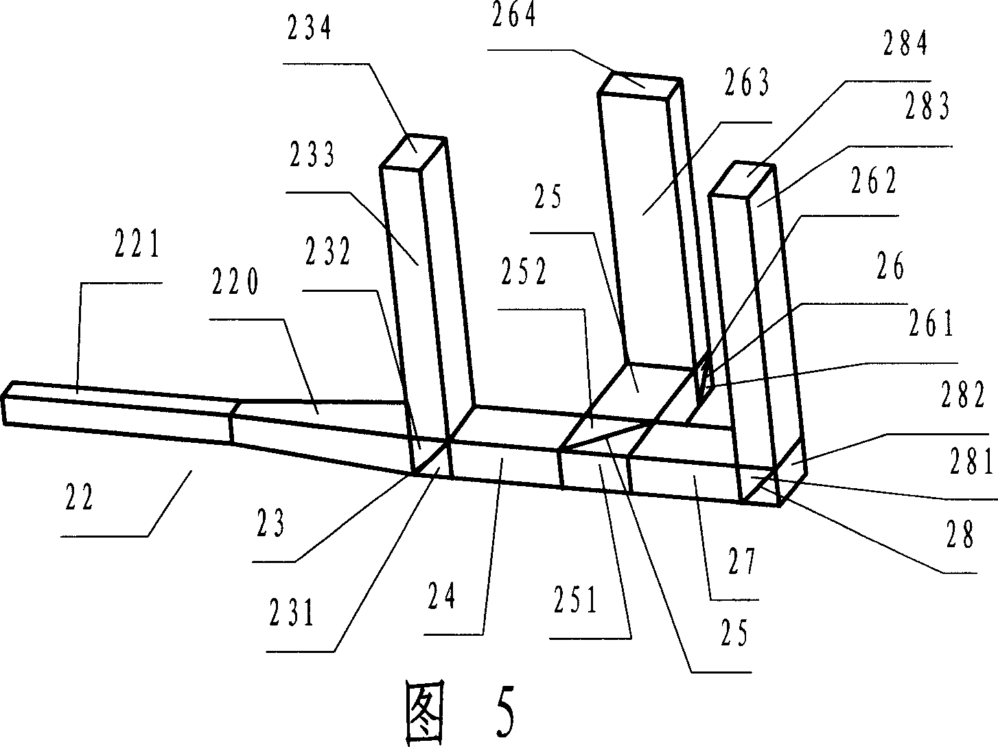
[0038] The assembly of this embodiment has the structure shown in FIG. 4 . The light guide rods, dichroic prisms, and reflective ribs that constitute the components of this embodiment are made of optical glass, and the incident light guide rod 22 is a straight prism 220 whose incident surface is smaller than the outgoing surface. Incident light guide rod 22, first connection light guide rod 24, second connection light guide rod 253, third connection light guide rod 27, first exit light guide rod 233, second exit light guide rod 263, third exit light guide rod The cross-section of the light rod 283 is rectangular, the dichroic film of the first dichroic prism 23 reflects blue light, transmits green light and red light, the dichroic film of the second dichroic prism 25 reflects green light, transmits red light, and the first reflective prism The reflective film of the second reflective prism 26 reflects green light, and the reflective film of the second reflective prism 28 refle...
PUM
 Abstract
Description
Claims
Application Information
 - R&D
- Intellectual Property
- Life Sciences
- Materials
- Tech Scout
- Unparalleled Data Quality
- Higher Quality Content
- 60% Fewer Hallucinations
Browse by: Latest US Patents, China's latest patents, Technical Efficacy Thesaurus, Application Domain, Technology Topic, Popular Technical Reports.
© 2025 PatSnap. All rights reserved.Legal|Privacy policy|Modern Slavery Act Transparency Statement|Sitemap|About US| Contact US: help@patsnap.com