Luminescence module and surface light source device

A technology for light-emitting modules and surface light sources, which is applied in identification devices, optics, optical components, etc., and can solve problems such as high cost, large mixing space, and poor luminous efficiency.

Inactive Publication Date: 2007-08-01
CORETRONIC
View PDF1 Cites 4 Cited by
  • Summary
  • Abstract
  • Description
  • Claims
  • Application Information

AI Technical Summary

Problems solved by technology

[0005] In the prior art, the light guide 110 does not guide the traveling direction of the light 50 well, and the light 50 is totally reflected in the light guide 110 many times, so that the luminous efficiency is not good
In addition, a single side-emitting LED package structure 120 can only emit light of a single wavelength, so it is necessary to provide different wavelengths of light thr...

Method used


Image

  • Luminescence module and surface light source device
  • Luminescence module and surface light source device
  • Luminescence module and surface light source device

Examples


no. 1 example

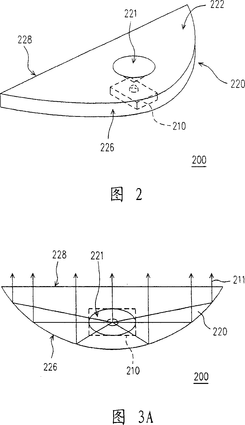
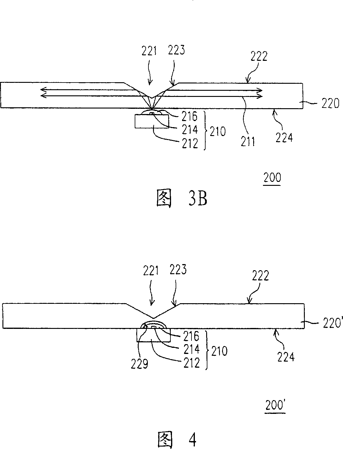
[0053] Please refer to FIG. 2 , FIG. 3A and FIG. 3B , FIG. 2 is a perspective view of the light emitting module according to the first embodiment of the present invention, FIG. 3A is a top view, and FIG. 3B is a structural cross-sectional view. The light emitting module 200 of the first embodiment of the present invention includes a light source group 210 and a light guide 220 . The light source group 210 is suitable for providing a light 211 , and the light guide 220 is disposed above the light source group 210 . Wherein, the light guide 220 has a top surface 222 and a light incident surface 224 opposite to each other, and a first reflective surface 226 and a light exit surface 228 opposite to each other, and the first reflective surface 226 and a light exit surface 228 are respectively connected to Between the top surface 222 and the light incident surface 224 , the two ends of the first reflective surface 226 are, for example, connected to the two ends of the light exit sur...

no. 2 example

[0061] Please refer to FIG. 4 , which is a structural sectional view of a light emitting module according to a second embodiment of the present invention. The light emitting module 200' of the second embodiment is similar to the above light emitting module 200, except that the light incident surface 224 of the light guide member 220' of the light emitting module 200' has a second recess 229, which is opposite to the first recess 221, The light source group 210 is embedded in the second recess 229 , so that the alignment between the light source group 210 and the light guide member 220 ′ is facilitated, and the assembly time is reduced.

no. 3 example

[0063] In this embodiment, the above-mentioned light emitting modules 200, 200' of the first embodiment and the second embodiment are applied to a surface light source device, and the surface light source device 300 includes a light guide plate 310 and a plurality of the above light emitting modules 200. The light emitting modules 200 are disposed on one side (as shown in FIG. 5 ) or both sides (as shown in FIG. 6 ) of the light guide plate 310, and the light 211 emitted from the light exit surface of the light guide member 220 of each light emitting module 200 is incident on the light guide plate. 310, and the light guide plate 310 is suitable for converting these light rays 211 into a surface light source with uniform brightness. The light guide 220 of each light emitting module 200 can be a separate part or integrally formed, and the light guide 220 and the light guide plate 310 of each light emitting module 200 can also be a separate part or integrally formed, when the ligh...


PUM


Abstract

This invention discloses one light module, which comprises one light source set and one conductive part, wherein, light source is to provide one light beam and the conductive part is set above light source set; light conductive part has relative one top surface, one light incidence surface and one first reflection surface and one light exit surface connected between top and incidence surface; top surface has one first concave with its surface of one second reflection surface for reflection light. This invention provides one surface light source device with light module.

Description

technical field [0001] The present invention relates to a light emitting module, in particular to a light emitting diode (Light Emitting Diode, LED) light emitting module and a surface light source device using the light emitting module. Background technique [0002] In recent years, due to the continuous improvement of the luminous efficiency of light-emitting diodes, light-emitting diodes have gradually replaced fluorescent lamps and incandescent bulbs in some fields, such as using light-emitting diodes as the backlight of liquid crystal displays. [0003] Please refer to FIG. 1A and FIG. 1B , which is a conventional light emitting module 100 disclosed in US Patent No. 6,598,998, which includes a light guide 110 and a plurality of side-emitting LED packaging structures 120 . The light guide 110 has a plurality of through holes 112 , and the LED packaging structure 120 is embedded in the through holes 112 . In addition, each LED packaging structure 120 includes a carrier 1...

Claims


Application Information

Patent Timeline
IPC IPC(8): G02F1/13357H01L33/00G02B1/10G09F9/00G02F1/1335
Inventor 刘明达萧增科周文彬侯腾超
Owner CORETRONIC
Why Eureka
Try Eureka