Clamping apparatus

A clamping device and clamping bolt technology, applied in the direction of positioning device, clamping, tool clamp, etc., can solve the problems of increasing the total cost of the clamping system, mechanical damage, etc.

Inactive Publication Date: 2007-08-08
F TOOL INT
View PDF1 Cites 5 Cited by
  • Summary
  • Abstract
  • Description
  • Claims
  • Application Information

AI Technical Summary

Problems solved by technology

[0004] In this type of connection, the lands are exposed and there is therefore a risk of mechanical damage
Moreover, all pallets used in the clamping device must have such lands, which requires an increase in the overall cost of the clamping system, since often a specific chuck element is equipped with multiple pallet elements

Method used


Image

  • Clamping apparatus
  • Clamping apparatus
  • Clamping apparatus

Examples


Embodiment Construction

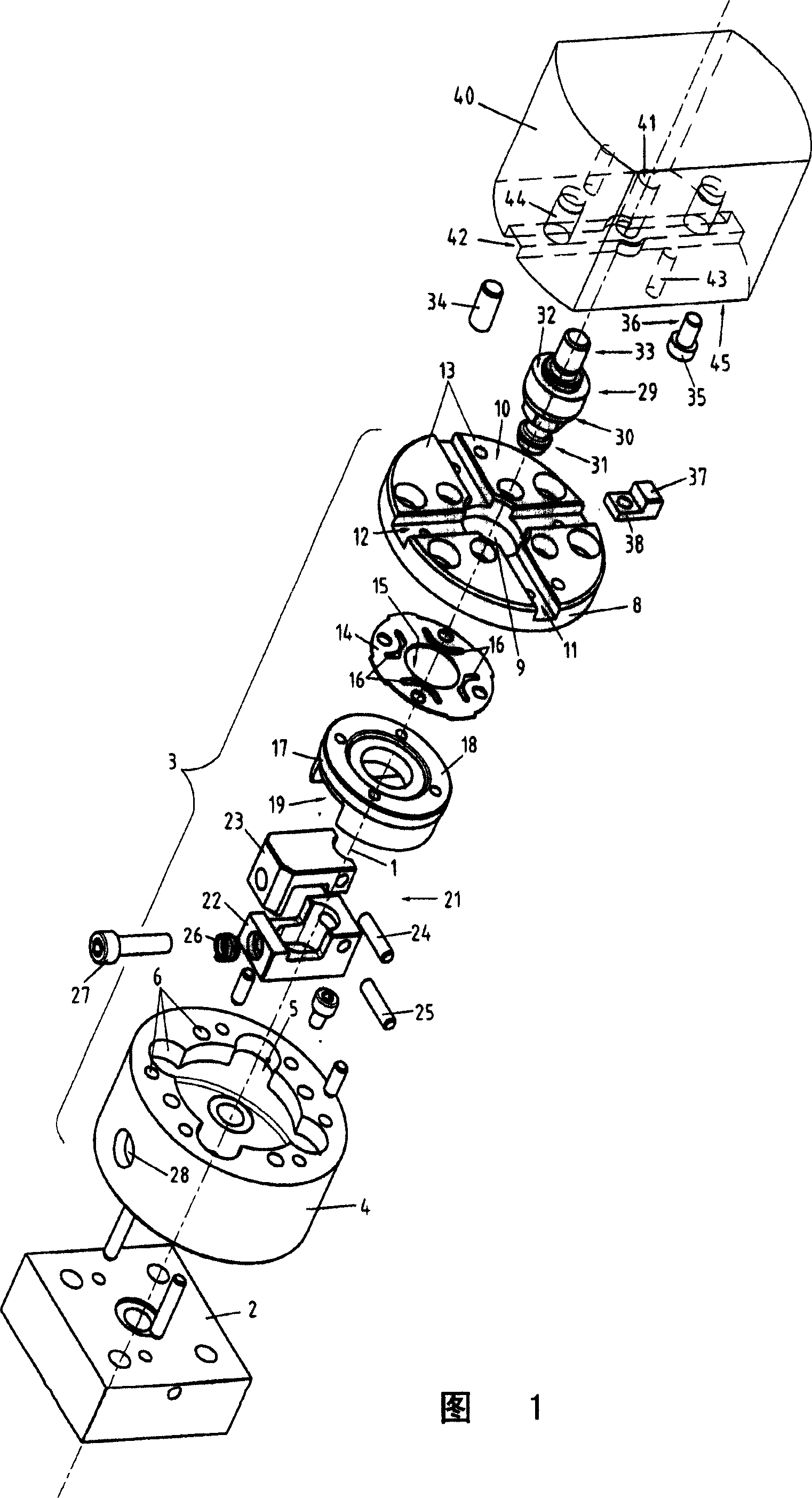
[0014] FIG. 1 shows an exploded perspective view of a clamping device suitable for clamping, for example, a component 40 on a chuck element 3 . The expression "member" should be understood as a general expression for the various parts that may be connected to the chuck element 3; in particular, the member 40 may be a workpiece, a tool or a pallet. Furthermore, it should be noted that members required to connect the chuck parts, such as screws, are not shown in the figures.

[0015] A longitudinal central axis extending through the center of the chuck 3 and of the clamping member 40 and coincident with the Z-axis is indicated generally by reference numeral 1 . It can be seen in FIG. 1 that the plate element 2 to which the chuck can be attached is situated below the chuck 3 . The plate element 2 is an example of a support device provided on a machine tool in which the device is used; in particular, the support device may be a machine tool platform or a casing of the machine too...


PUM


Abstract

The clamping apparatus comprises a chuck member for holding an element to be clamped thereto that is provided with a centering disc member that is elastically resilient in Z-direction and that defines at least one aperture. The element to be clamped is provided with a clamping bolt member having a centering portion in the shape of a truncated cone. Upon insertion of the clamping bolt member into the aperture of the centering disc member, the centering portion engages the edge of the aperture in the centering disc and aligns the element to be clamped in the X- and Y-directions. The centering disc member is located behind an end plate member of the chuck member, and the surface of the end plate member constitutes the Z-reference for the element to be clamped. The end plate member is provided with an aperture through which the clamping bolt member can be inserted into the aperture of the centering disc member.

Description

technical field [0001] The invention relates to a clamping device comprising a chuck element adapted to fix a component to be clamped and having a first centering device, and a component to be clamped with a first centering device adapted to be arranged on the chuck. A second centering device cooperates with the centering device so that the component to be clamped is aligned in the X and Y directions by clamping said component on the chuck element. [0002] The clamping device is preferably used to clamp a component at a precisely defined location in the machining area of ​​the machine tool, whereby the component can be formed by a workpiece, a tool or a pallet suitable for receiving a workpiece or a tool. Typically, the chuck element is attached to the machine platform in the machining area of ​​the machine tool, and the component to be clamped is releasably attached to the chuck element. Background technique [0003] Document EP-A-111092 discloses a clamping device for fo...

Claims


Application Information

Patent Timeline
Patent Type & Authority Applications(China)
IPC IPC(8): B23Q16/08F16B2/02
CPCB23Q1/0072Y10T279/17761B23B31/06B23B29/04B23Q3/12
Inventor F·特罗克斯勒
Owner F TOOL INT
Why Eureka
Try Eureka